contact@canrd.com
 +86 18928276992
 Home/Resources/Knowledge/Cell Fabrication/How Are Lithium-Ion Pouch Cells Made? Complete Step-by-Step Guide from Slurry Mixing to Cell Testing
How Are Lithium-Ion Pouch Cells Made? Complete Step-by-Step Guide from Slurry Mixing to Cell Testing
Canrd August 1, 2026 616
1. Introduction: 3 Core Manufacturing Stages & Full Process Roadmap
Lithium-ion pouch cell manufacturing is divided into three standardized industrial modules: Electrode Manufacturing, Dry Cell Assembly, and Cell Finishing & Electrochemical Testing. Every upstream parameter deviation cascades into downstream finished cell defects (leakage, swelling, low capacity, high internal resistance, abnormal self-discharge).
Complete linear manufacturing flow :
Cathode/Anode Slurry Mixing → Coating & Oven Drying → Calendering → Automatic Slitting → Tab Welding & Insulation Taping → Semi-Automatic Winding → Electrical Short-Circuit Screening → X-Ray Overhang Inspection → Aluminum Laminate Pouch Deep Drawing → Top / Side / Corner Pre-Sealing → Three-In-One Internal Resistance Test → Vacuum Pre-Injection Baking → Dry-Room Electrolyte Filling → Temporary Vacuum Sealing → Hot & Cold Press Shaping → Resting Wetting → Formation Activation → Degassing & Final Edge Sealing → Edge Folding → Inkjet Coding → Capacity Grading → Constant-Temperature Aging → OCV K-Value Self-Discharge Screening → Finished Cell Warehousing
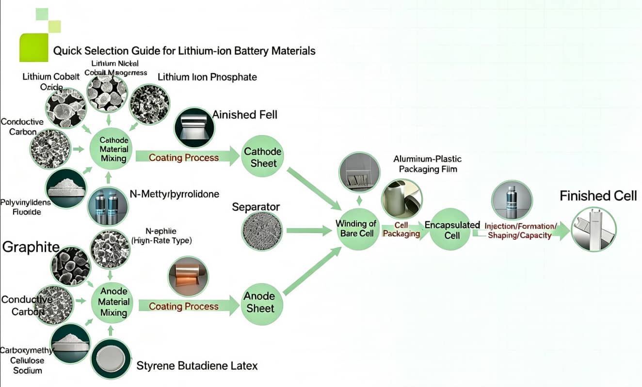
Module 1: Electrode Manufacturing
This module fabricates qualified positive (cathode) and negative (anode) electrode rolls, the foundation of all cell electrochemical performance. Key sub-processes: slurry mixing, coating & drying, calendering, slitting, tab welding & insulation taping.
1.1 Slurry Mixing
Core Function
Homogenize active materials, conductive additives, binders, and solvents into uniform, bubble-free, long-term stable suspensions for electrode coating. Cathode and anode slurry formulations adopt completely different systems.
Raw Material Formula Split
- Cathode Slurry: NCM/LCO/LFP active material conductive carbon black PVDF binder NMP organic solvent
- Anode Slurry: Graphite / Silicon-Carbon composite active material conductive carbon CMC thickener SBR water-based latex binder
Standard Production Equipment
Vacuum planetary mixers (35L / 100L / 200L / 300L volume grades)
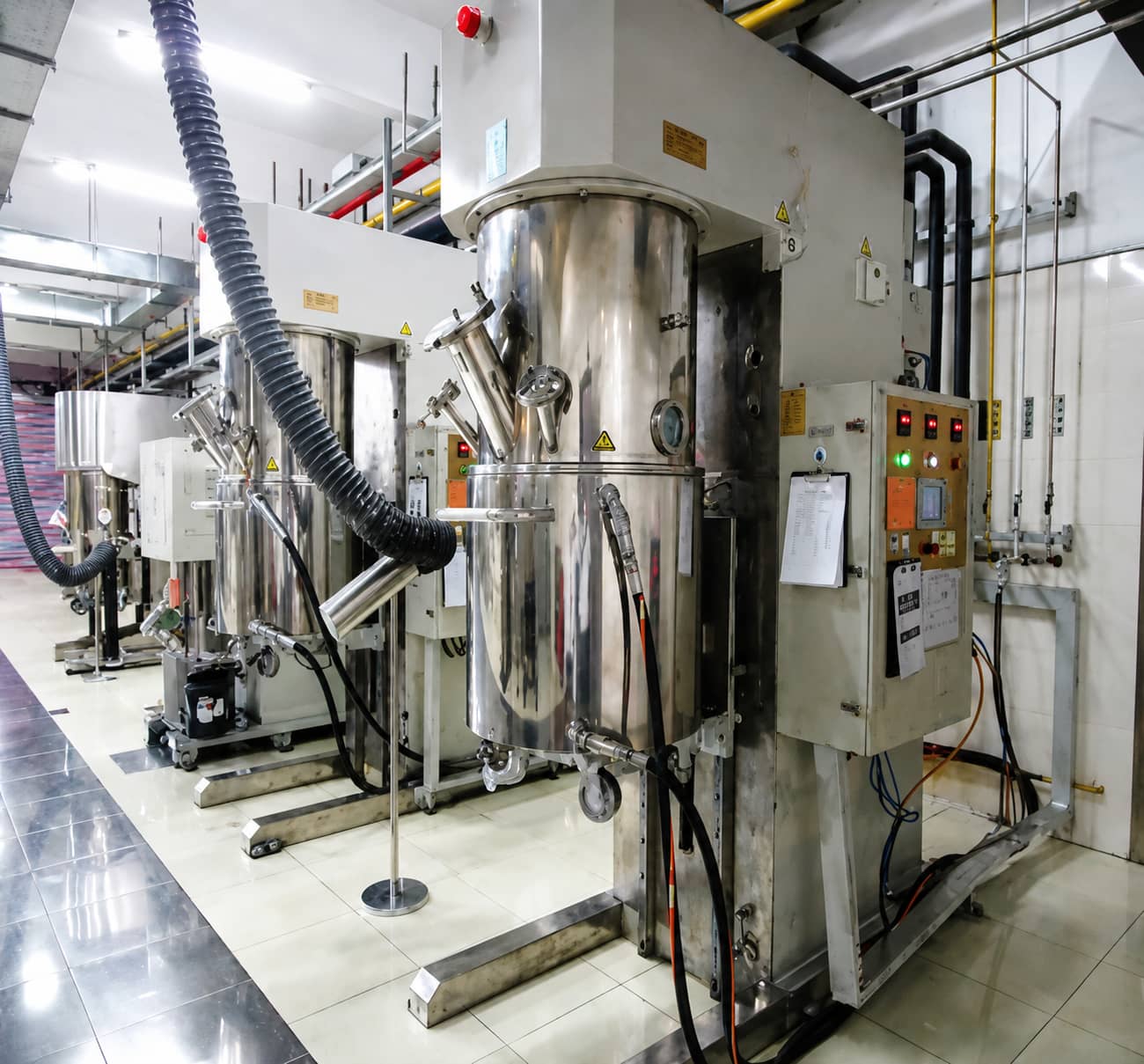
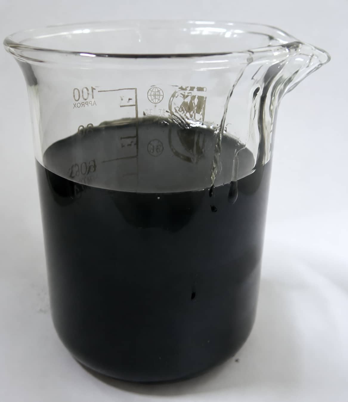
Mandatory Pre-Coating QC Indicators
Slurry solid content, viscosity, dispersion fineness, bubble content, sedimentation stability
Upstream Defect Downstream Consequence
Poor slurry dispersion → electrode uneven coating, high cell internal resistance; excessive bubbles → coating pinholes; severe sedimentation → batch capacity inconsistency
For detailed mixing parameter windows, defect elimination and PVDF binder dissolution workflow, read our dedicated article: [Battery Manufacturing Process: Battery Slurry Mixing]
1.2 Electrode Coating & Oven Drying
Core Function
Uniformly apply qualified slurry onto current collector foils and evaporate all solvent via segmented drying ovens
- Cathode substrate: 12μm aluminum foil
- Anode substrate: 8μm copper foil
Standard Production Equipment
Integrated coating machine split into feeding station, coating head control zone, and multi-stage long drying oven

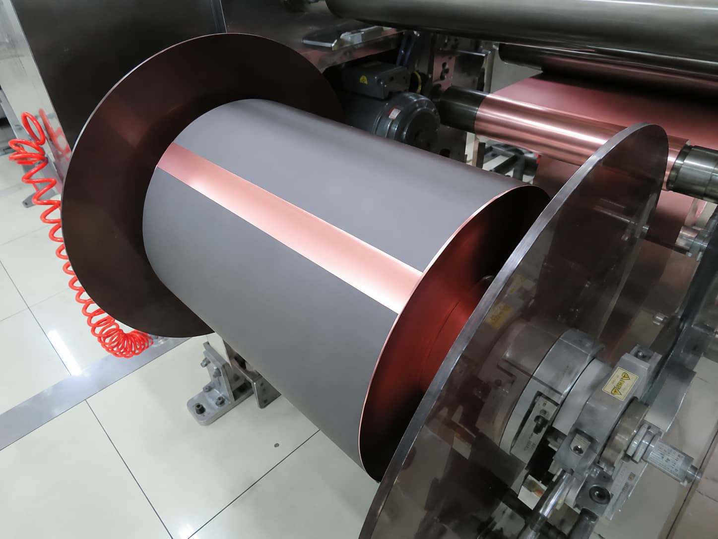
Mandatory QC Indicators
Single/double-side electrode areal loading, cross-web thickness uniformity, oven temperature gradient, coating surface appearance
Critical Safety Rules
Operators must never place fingers under coating rollers; hard tools cannot strike roller surfaces to prevent permanent surface scratches
Uneven coating loading → large cell capacity deviation; incomplete drying → residual solvent causes post-production swelling
Read full coating defect troubleshooting: Lithium-ion Electrode Coating Defects & Process Optimization
1.3 Calendering (Rolling)
Core Function
Compress dried coated electrodes to target compact density, balance volumetric energy density and electrode porosity (over-calendering reduces ion transport channels and worsens rate performance)
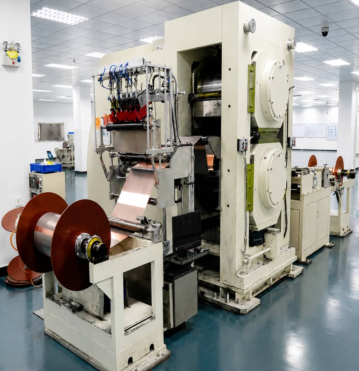
Standard Production Equipment
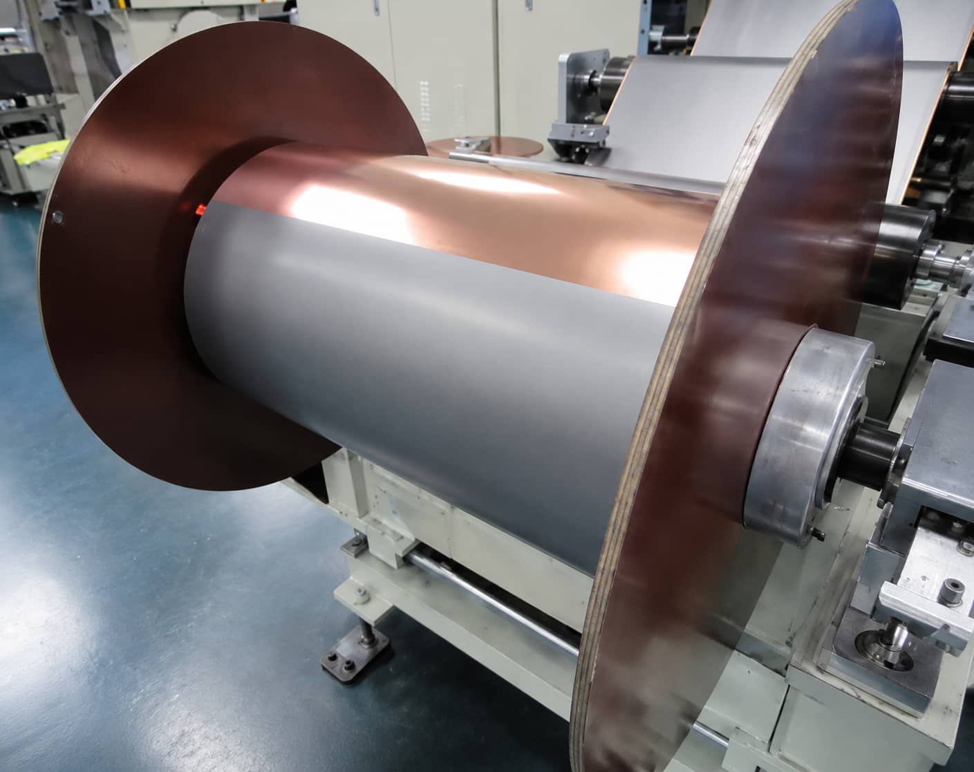
Three-section roller press machine: material feeding station, pressing roller zone, finished electrode winding station
Mandatory QC Indicators
Post-calendering electrode thickness, surface appearance (no cracking, powder shedding, longitudinal stripes)
Critical Safety Rules
Forbid inserting hands into roller feeding inlet; blades cannot be used to scrape roller surfaces
Upstream Defect Downstream Consequence
Unstable calender gap → thickness inconsistency; over-compaction → low cycle life, high DCIR
Dedicated guide: Battery Electrode Calendering Process & Porosity Control
1.4 Automatic Slitting Tab Welding & Insulation Taping
1.4.1 Automatic Slitting
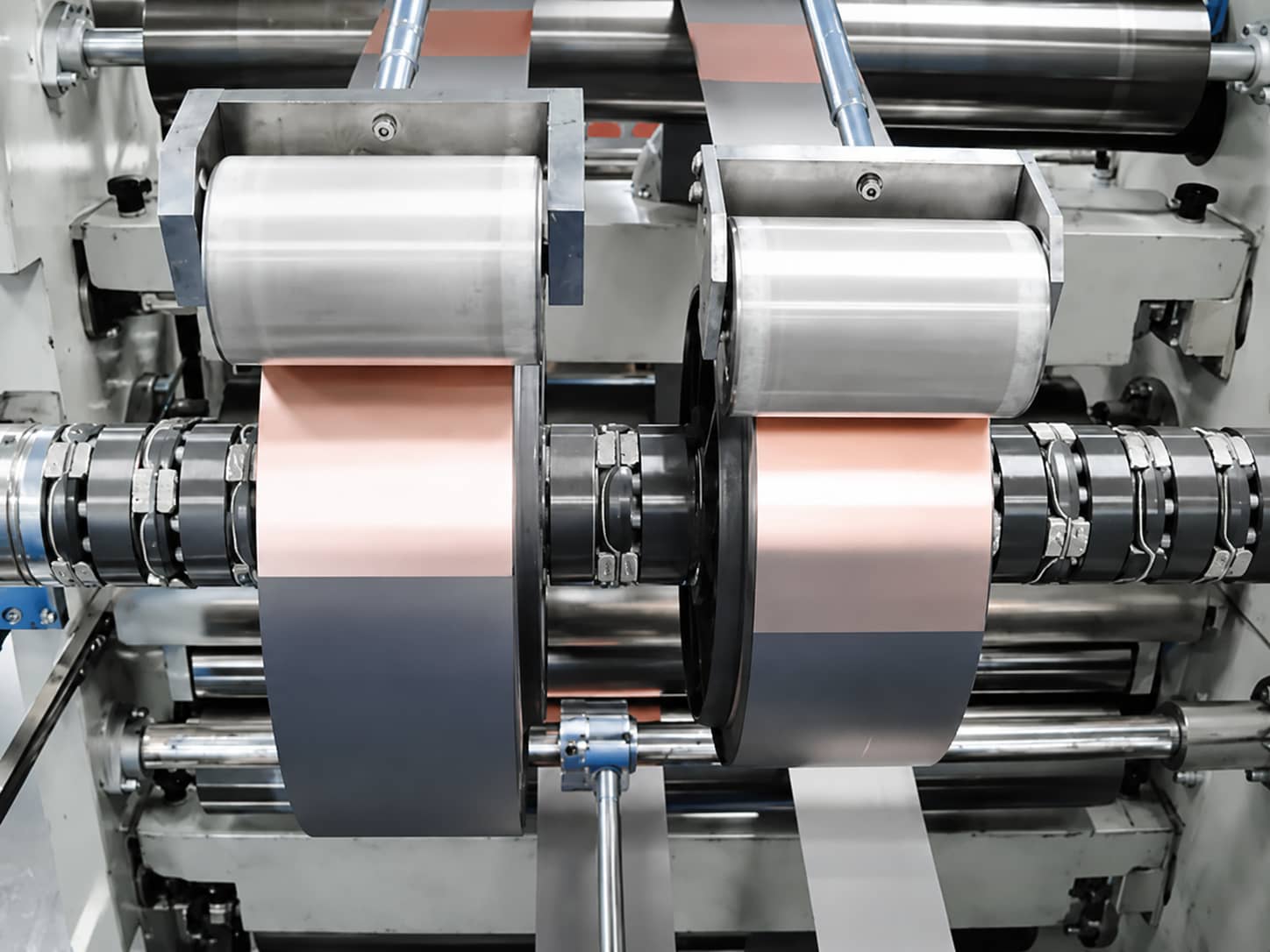
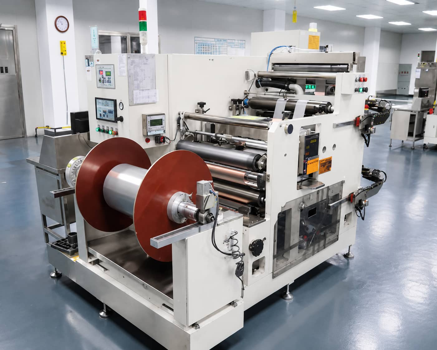
Cut large calendered electrode master rolls into narrow small rolls matching winding dimension
Mandatory QC Indicators
Finished small roll width, edge burr height, winding neatness Safety Rule: Never touch slitting blades or blade holders during operation
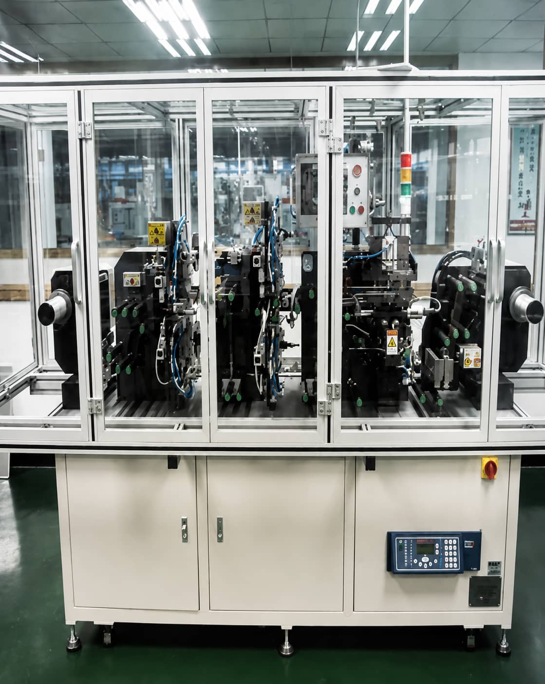
1.4.2 Tab Welding & CPP Insulation Taping
Weld metal current collector tabs to slit electrodes and attach insulating CPP tape over welding zones to prevent separator piercing from welding burrs
- Cathode tab material: Aluminum (Al) strip
- Anode tab material: Nickel (Ni) strip
Mandatory QC Indicators
Tab welding tensile strength, welding imprint appearance, CPP tape offset distance, exposed foil width outside insulation Safety Rule: Fingers are prohibited from entering tab feeding conveyor zones
Upstream Defect Downstream Consequence
Excessive slitting/tab welding burrs → internal micro-short circuits, elevated self-discharge; weak tab welds → abnormally high cell internal resistance
Related article: Electrode Slitting, Tab Welding & Insulation Taping Troubleshooting
Module 2: Cell Assembly (Dry Room Environment Required)
All assembly processes operate in low dew-point dry rooms to eliminate moisture contamination, which triggers electrolyte decomposition and cell swelling. Core steps: semi-automatic winding, dual electrical screening, X-Ray alignment inspection, aluminum laminate pouch deep drawing, multi-stage thermal sealing.
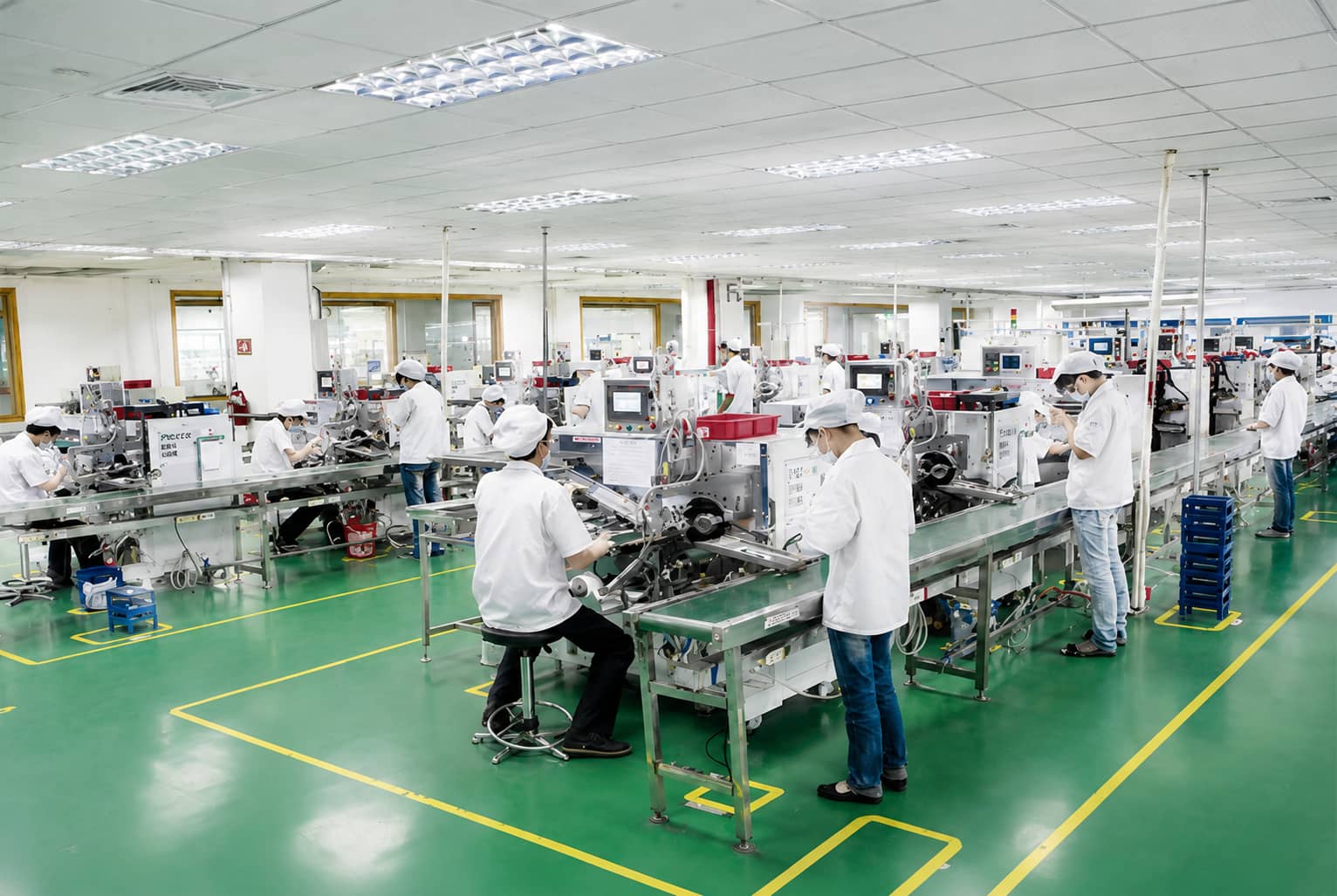
Stack positive electrode, separator, and negative electrode layer-by-layer to form a complete jelly roll bare cell
Mandatory QC Indicators
Finished jelly roll width/thickness, positive/negative electrode overhang margin, center distance between dual tabs, lengthwise electrode offset Key Design Rule: Anode active area must fully cover cathode to avoid lithium plating risk Safety Rule: Keep hands away from separator cutting blades
2.2 Electrical Short-Circuit & Internal Resistance Screening
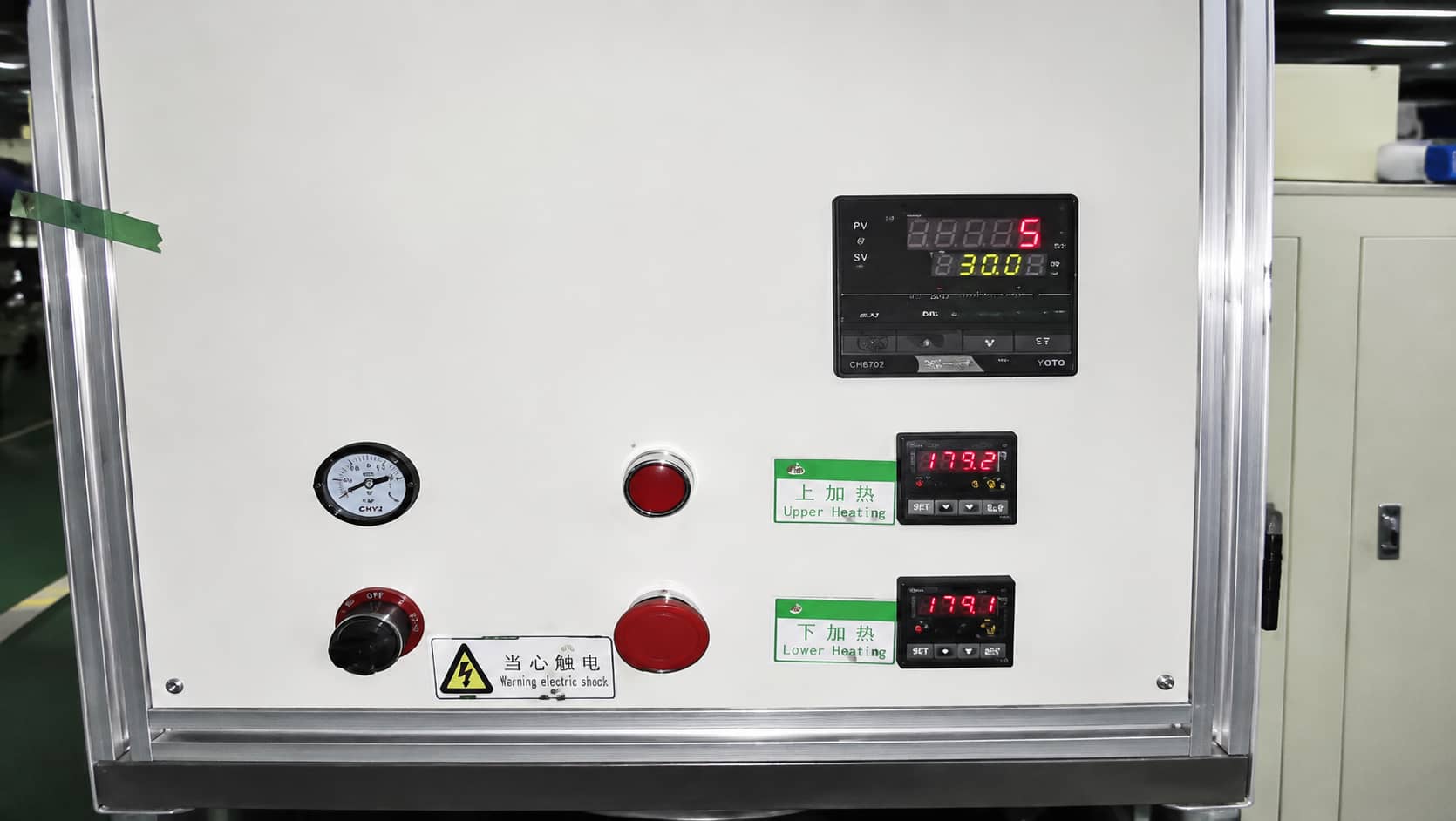
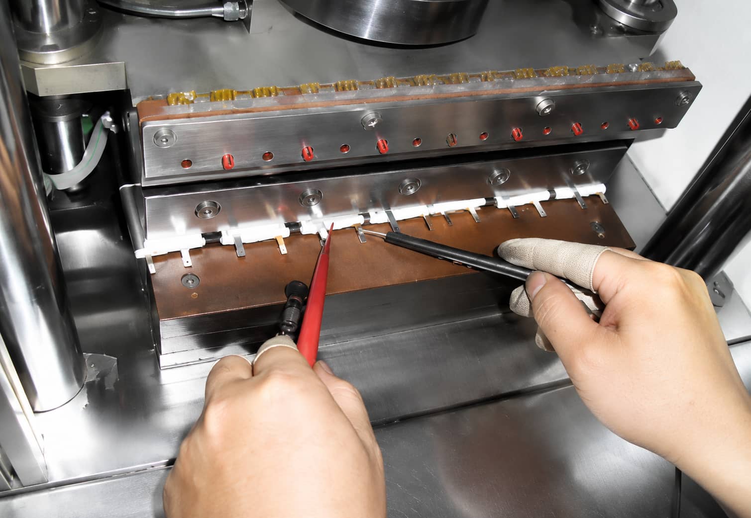
Conduct dual-tab insulation and short-circuit testing on wound jelly rolls to eliminate micro-short defective cells before packaging
Mandatory QC Indicators
Calibrated internal resistance threshold, insulation breakdown value Safety Rule: Do not place hands between upper/lower test pressing plates
2.3 X-Ray Overhang Inspection
Non-destructive X-ray imaging verifies cathode/anode alignment offset; rejects cells with unqualified electrode overhang
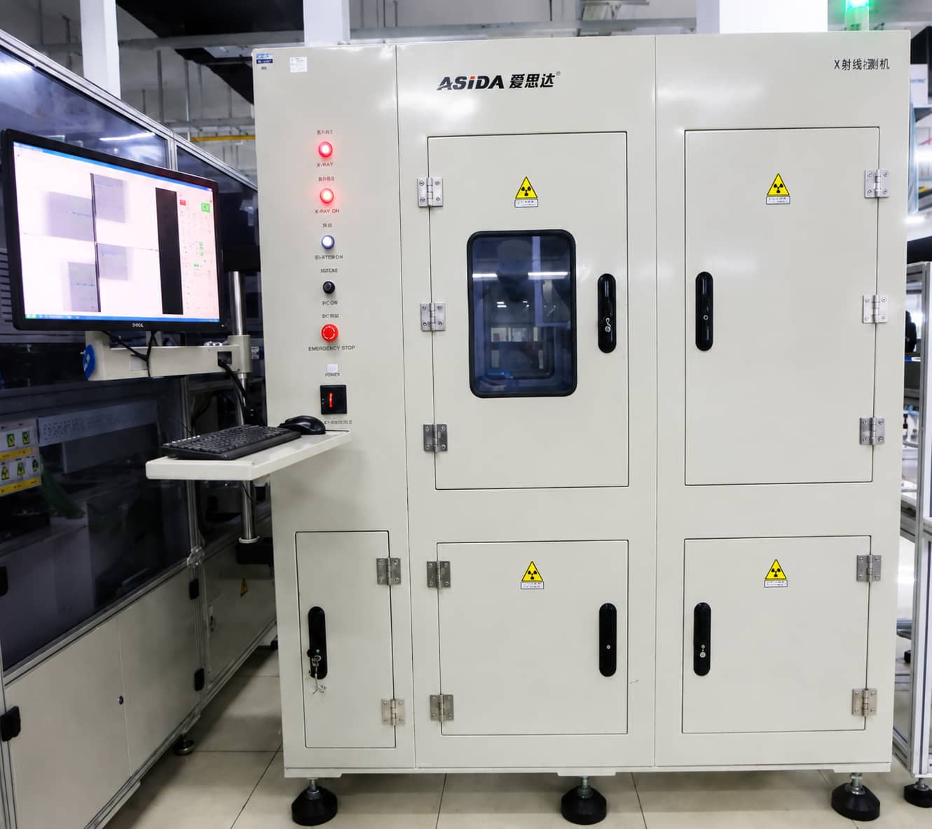
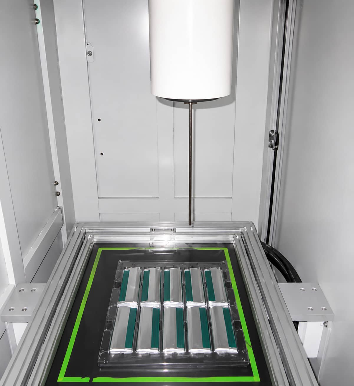
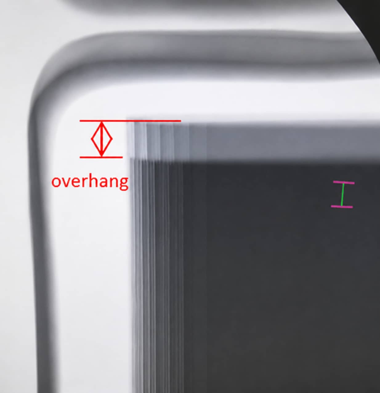
Mandatory QC Indicators
Horizontal and vertical electrode overhang dimension Safety Rule: Machine access doors must remain fully closed during X-ray emission to avoid radiation exposure
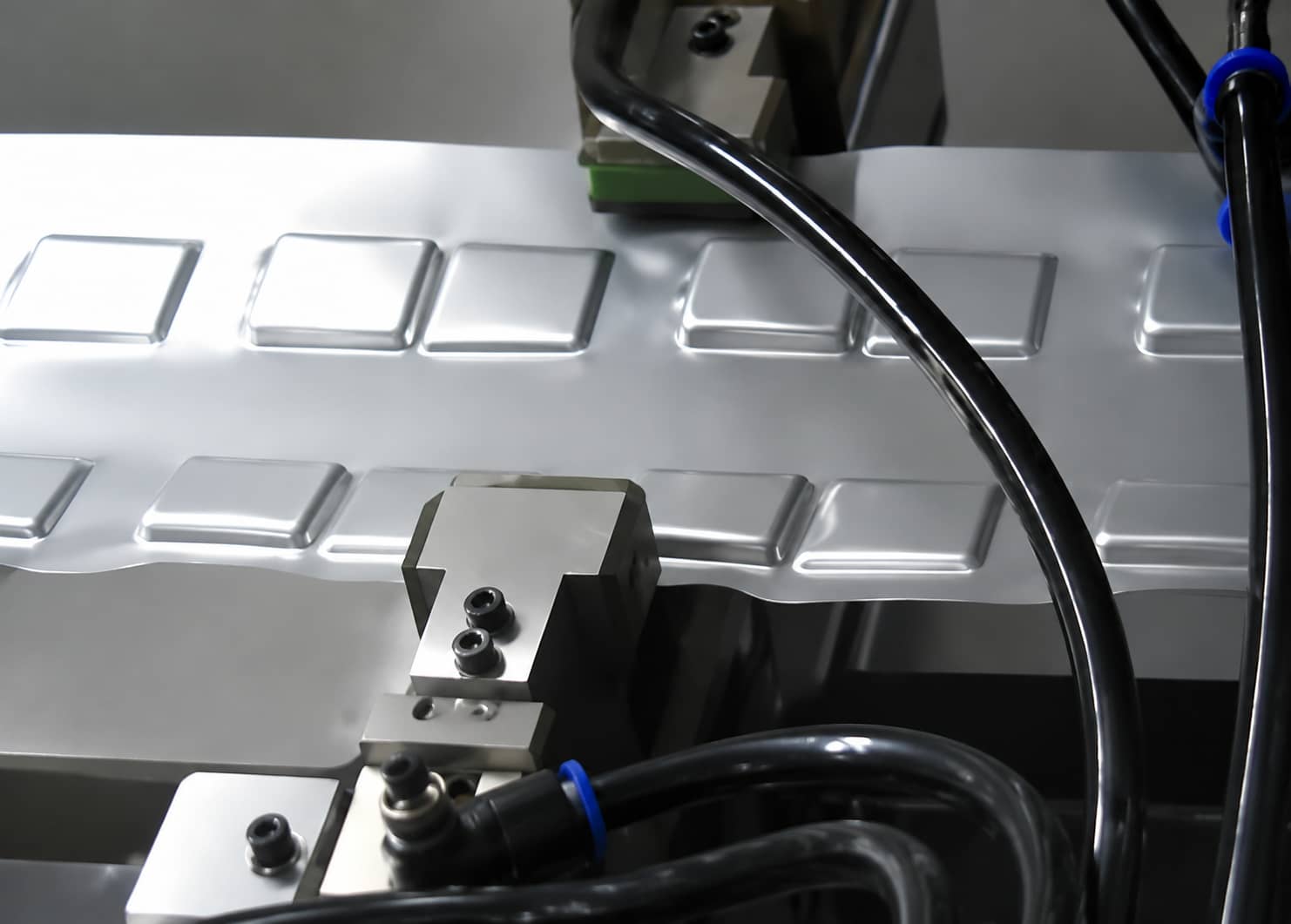
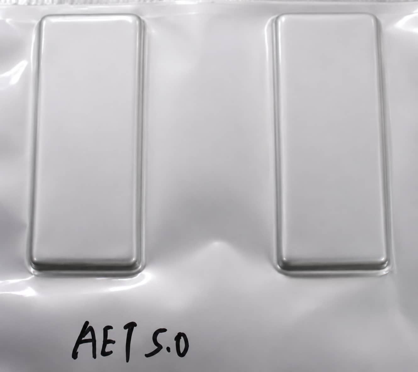
2.4 Aluminum Laminate Pouch Deep Drawing (Punch Forming)
Stretch flat three-layer aluminum laminate film into concave pockets to accommodate wound jelly rolls
Laminate Film Structure (Training Example Specification, Not Universal Industry Standard)
Outer Nylon layer (21μm) | Middle moisture-barrier Aluminum layer (33μm) | Inner heat-sealable PP layer (32μm); total thickness 85μm
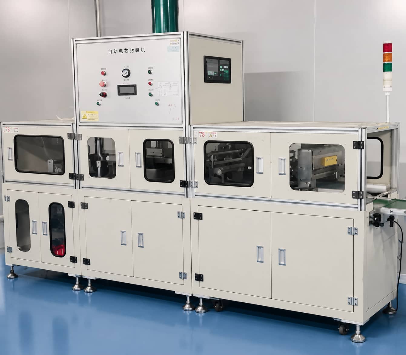
Mandatory QC Indicators
Pocket depth, four-corner mold R-angle dimension, surface crack-free appearance Safety Rule: Never insert hands between upper/lower forming molds
Forming Defect Risk
Excessive corner strain creates micro-cracks, leading to finished cell electrolyte leakage
2.5 Multi-Stage Thermal Sealing (Top Sealing → Side Sealing → Corner Pre-Sealing)
Place jelly rolls into formed pockets and perform sequential heat fusion sealing on the pouch’s PP inner layer

Mandatory QC Indicators
Seal cross-section thickness, sealing surface cleanliness, tab exposed PP insulation width, internal/external unsealed margin dimensions Core Anti-Leakage Principle: Complete PP layer fusion without foreign contamination between sealing surfaces Safety Rule: Safety light curtains must be validated functional per shift; hands cannot enter heat sealing head range
Critical Anti-Corrosion Design
Reserved unsealed dimensions A/B/C/D/E (training case range 0.3~1.0mm for A/C/D/E, B > 0mm) isolate Al tab metal from electrolyte to prevent electrochemical corrosion
Full sealing defect analysis: Pouch Cell Sealing Encapsulation Process Training
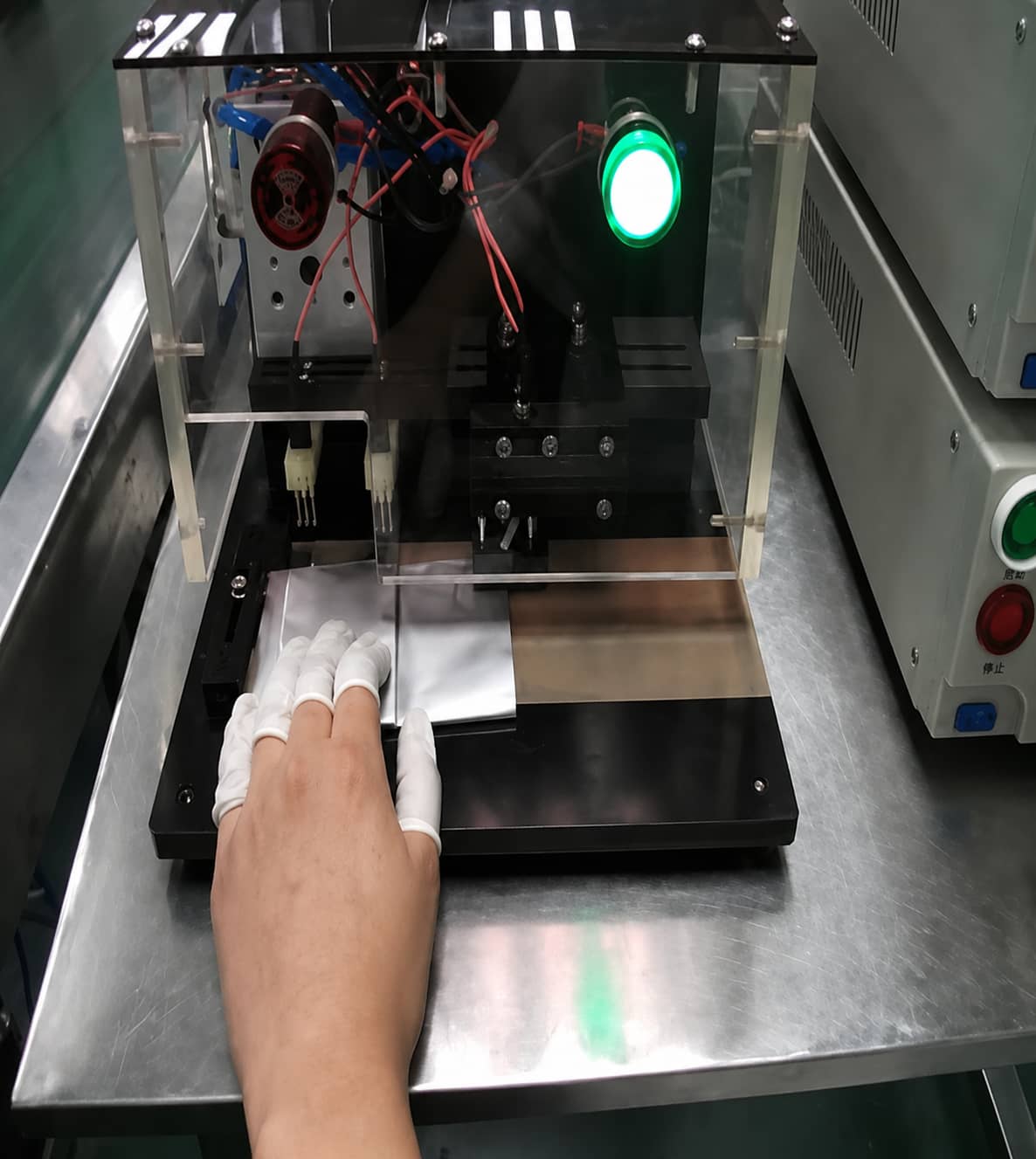
2.6 Three-In-One Combined Testing
Secondary internal resistance and insulation screening after preliminary pouch sealing
Mandatory QC Indicators
Calibrated internal resistance benchmark value Safety Rule: Fingers must stay clear of test probes and cutting lancets
Module 3: Cell Finishing & Electrochemical Testing
Post-sealing wet processing, activation, degassing, and performance grading; all electrolyte injection operations require strict dry-room low water/oxygen ppm control.
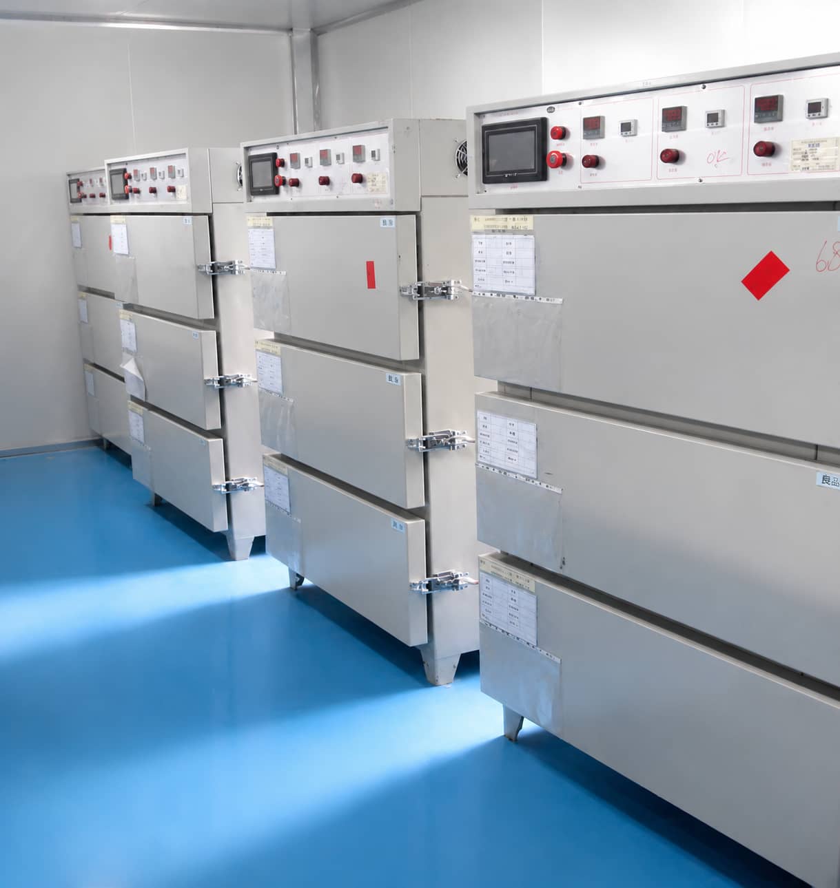
3.1 Vacuum Pre-Injection Baking
Remove residual moisture from sealed semi-finished cells to prevent LiPF6 electrolyte hydrolysis and gas generation
Mandatory QC Indicators
Baking temperature, holding vacuum level, heating/cooling cycle time, electrode residual moisture content Safety Rule: Heat-resistant gloves are mandatory when retrieving high-temperature baked cells to avoid burns
3.2 Electrolyte Filling & Temporary Vacuum Sealing
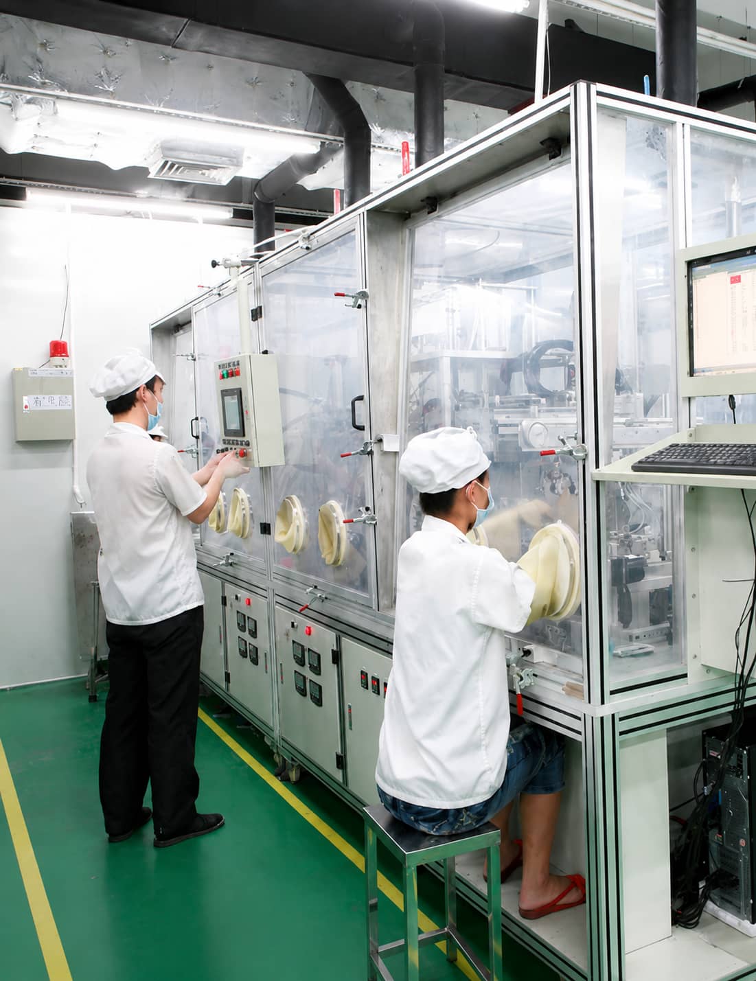
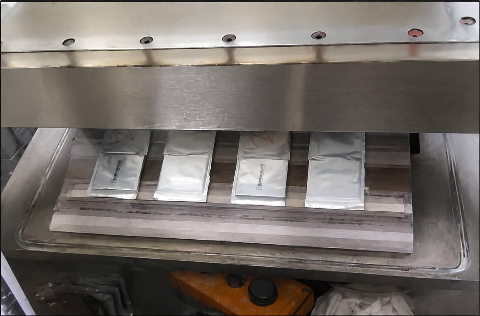
Inject calibrated precise electrolyte mass into baked cells inside fully enclosed glove boxes, then evacuate gas bags and perform temporary heat sealing
Mandatory QC Indicators
Liquid injection pump weight accuracy, temporary seal thickness, vacuum evacuation efficiency
After temporary sealing, cells rest for scheduled time to enable full electrolyte penetration into electrode and separator pores
3.3 Hot & Cold Press Shaping
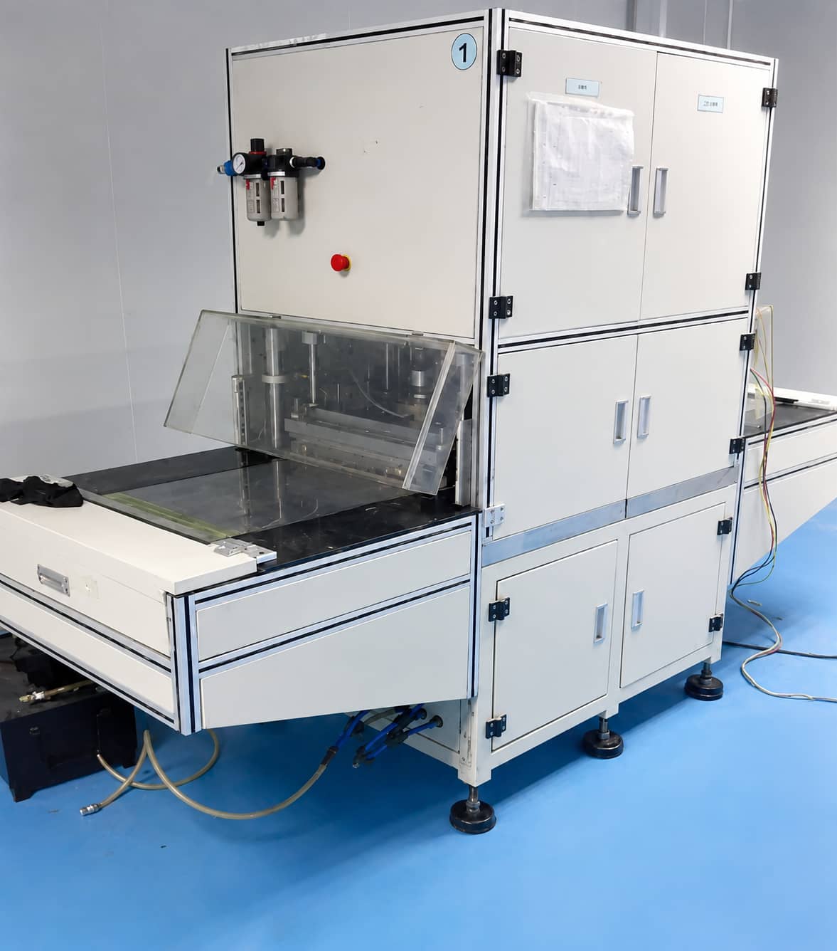
Dual-stage hot then cold pressing standardizes finished cell thickness and eliminates internal air gaps after electrolyte wetting
Mandatory QC Indicators
Hot/cold pressing air pressure, holding time, upper/lower pressing plate parallelism Safety Rule: Verify safety light curtain integrity before every production shift
3.4 Formation Activation
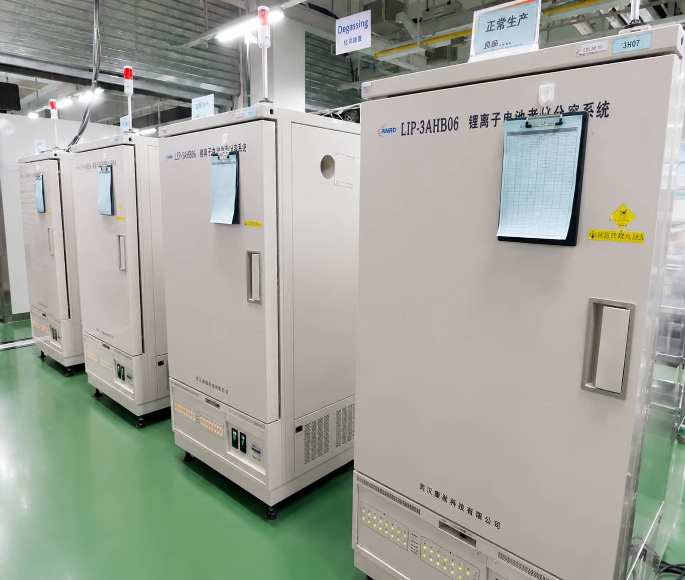
Programmed low-speed charge-discharge cycles to activate lithium ion migration and form stable SEI solid electrolyte interphase on anode surfaces
Mandatory QC Indicators
Formation step voltage/current precision, constant cabinet ambient temperature Key Note: Silicon-carbon composite anodes require adjusted low-current formation curves to mitigate severe volume expansion and particle pulverization
Dual dedicated formation guides: SEI Formation & Gas Generation Mechanism | Battery Formation Current/Temperature Parameter Tuning
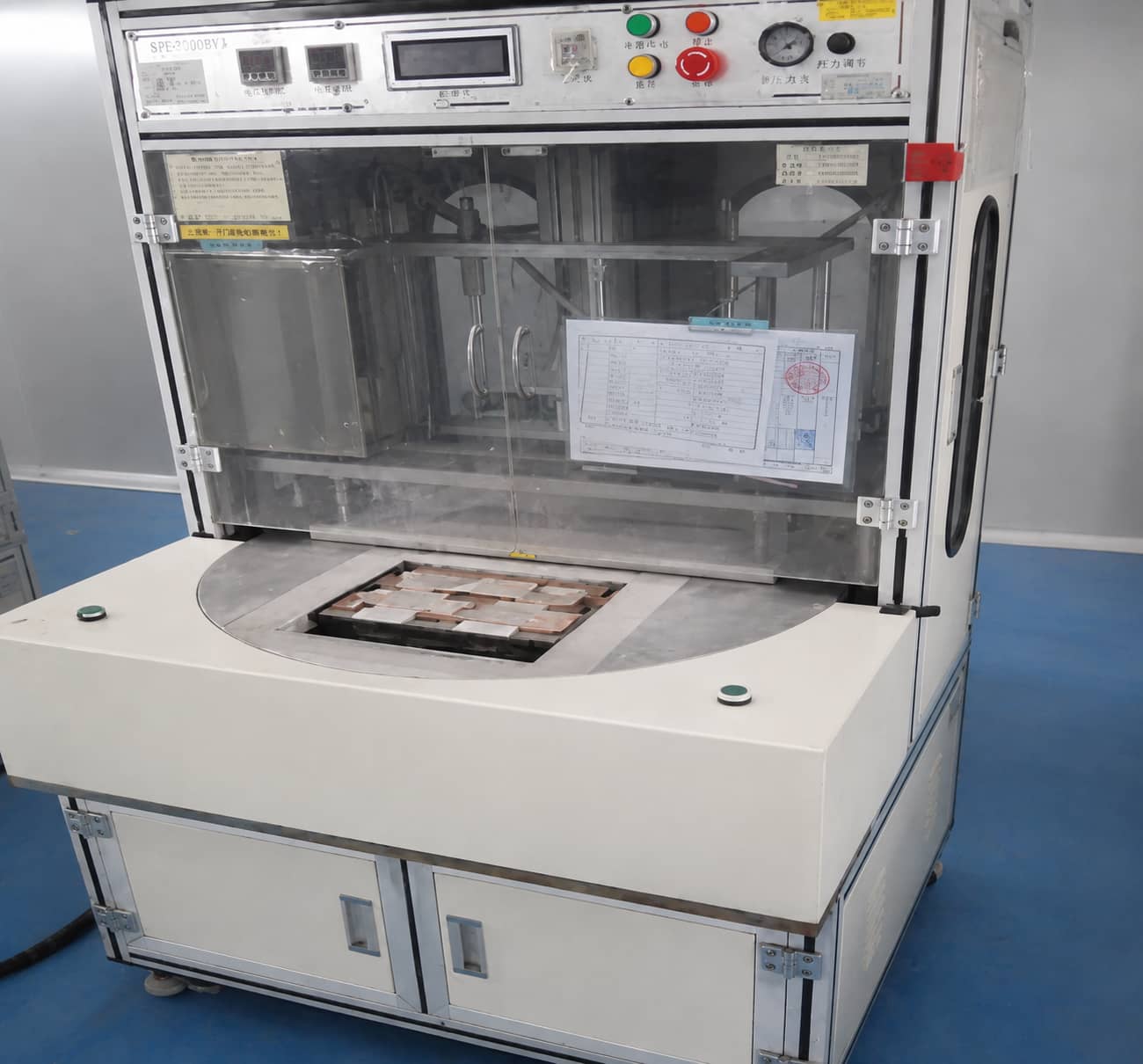
3.5 Degassing & Final Edge Sealing (DEG Secondary Sealing)
Extract formation-generated internal gas and excess electrolyte from gas pockets, trim redundant film, and execute permanent final sealing
Mandatory QC Indicators
Gas extraction completeness, final seal thickness, finished cell dimensional tolerance Defect Consequence: Incomplete degassing leads to permanent pouch swelling, thickness out-of-specification
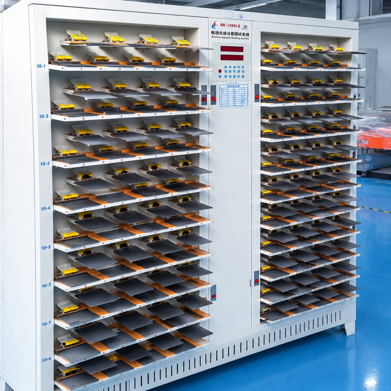
3.6 Capacity Grading
Full charge-discharge cycling to test actual discharge capacity and group cells into uniform capacity bins for consistent PACK assembly
Mandatory QC Indicators
Cabinet voltage/current calibration accuracy, cell capacity bin classification range
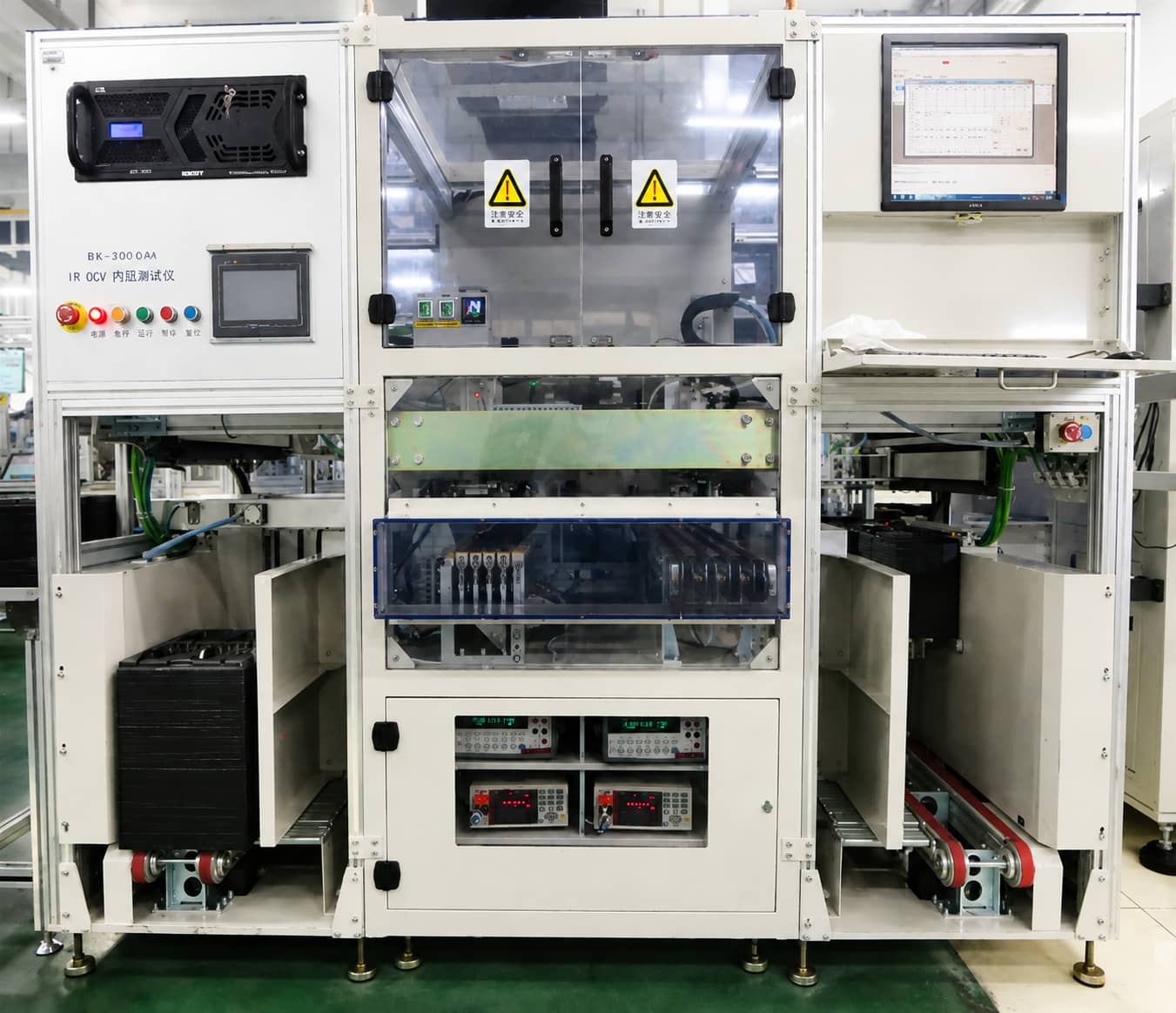
3.7 Constant-Temperature Aging & OCV Self-Discharge Screening
Store cells under stable temperature for fixed aging duration, then measure OCV voltage drop rate (K-value) to filter cells with abnormal self-discharge
Mandatory QC Indicators
Fixed voltage test interval, constant-temperature testing environment Critical Note: High OCV decay (elevated K-value) only indicates potential self-discharge risks; root causes include micro-shorts, sealing micro-leakage, or unstable SEI films and require further failure dissection verification
3.8 Post-Processing Auxiliary Steps
Edge heating folding, inkjet coding, finished cell sorting and warehousing complete the full manufacturing lifecycle
4. Cross-Process Defect Tracing Cheat Sheet
This table maps finished cell abnormal phenomena to priority upstream process inspection links and required verification evidence, avoiding single-cause oversimplification of failures.
| Finished Cell Abnormality | Priority Upstream Processes to Trace | Key Verification Evidence Items |
|---|---|---|
| Electrolyte leakage | Pouch forming, top/side sealing, corner pre-sealing, degassing final seal | Pouch corner micro-cracks, sealing surface foreign contamination, PP layer incomplete fusion, tab insulation offset dimension |
| Post-formation pouch swelling | Pre-injection baking moisture, electrolyte injection, formation curve, degassing efficiency | Karl Fischer residual moisture test, electrolyte injection weight, formation overcharge risk, gas residual after DEG |
| Low discharge capacity | Slurry mixing dispersion, coating areal loading, winding overhang matching, electrolyte wetting | Slurry fineness test, cross-web coating thickness, X-Ray N/P overhang offset, electrolyte penetration uniformity |
| High ACIR/DCIR internal resistance | Slurry conductive agent dispersion, tab welding, calendering compactness, electrolyte wetting | Slurry agglomeration inspection, tab welding tensile force, electrode porosity, insufficient soaking time |
| Abnormal OCV K-value (fast self-discharge) | Slitting/tab welding burrs, winding alignment, sealing integrity, formation SEI stability | Burr height measurement, X-Ray electrode offset, seal cross-section delamination, formation gas volume |
| Rapid cycle capacity decay | Silicon-carbon/graphite anode matching, formation current, PVDF binder dosage, electrolyte injection coefficient | Anode expansion performance, formation charging rate, coating binder proportion, residual electrolyte quantity |
| Internal micro-short circuit | Slitting edge burrs, tab welding burrs, winding misalignment, pouch sealing foreign debris | Burr microscopic imaging, X-Ray electrode overlap, sealing surface particle contamination |
| Finished cell thickness discrete deviation | Coating thickness, calender gap, hot/cold pressing pressure, formation SOC state | Full electrode thickness log, calender daily calibration, pressing plate parallelism, formation cut-off voltage consistency |
5. Process-Stage Input / Output / Risk Summary Table
Quick reference for quality control engineers to grasp each module’s core deliverables and failure risks
| Manufacturing Module | Core Input Material | Qualified Output Product | Main Inherent Process Risks | Linked In-Depth Article |
|---|---|---|---|---|
| Slurry Mixing | Active powder, conductive carbon, binder, solvent | Homogeneous bubble-free electrode slurry | Agglomeration, sedimentation, viscosity drift | Battery Slurry Mixing Process |
| Electrode Coating | Finished slurry, aluminum/copper foil | Uniform coated dry electrode rolls | Pinholes, coating streaks, powder shedding | Electrode Coating Defects Troubleshooting |
| Calendering | Dried coated electrodes | Compacted electrode with target porosity | Electrode cracking, uneven thickness | Electrode Calendering Guide |
| Slitting & Tabbing | Calendered master electrode rolls | Narrow tabbed insulated electrode strips | Excessive edge burr, weak tab welds | Slitting & Tab Welding Process |
| Winding & Inspection | Tabbed electrodes, separator film | Defect-free aligned jelly roll | Electrode overhang mismatch, micro-shorts | Winding & X-Ray Alignment QC |
| Pouch Sealing | Aluminum laminate film, jelly roll | Preliminarily sealed dry cell | Corner cracking, incomplete PP fusion, tab corrosion | Pouch Cell Encapsulation Training |
| Baking & Filling | Sealed semi-finished cell, electrolyte | Moisture-free electrolyte-filled cell | Residual moisture, uneven electrolyte injection | Vacuum Baking & Electrolyte Filling |
| Formation & DEG | Wet injected cell | Activated degassed cell pouch | Unstable SEI, trapped formation gas | Formation Part 1 / Formation Part 2 |
| Grading & OCV Screening | Degassed finished cells | Capacity-grouped low self-discharge cells | Capacity discrete distribution, misjudged K-value | Cell Grading & OCV Testing Standard |
6. Conclusion & Canrd One-Stop Manufacturing Support
The full lithium-ion pouch cell manufacturing workflow operates as a tightly interlocked closed quality loop across electrode fabrication, dry assembly, and electrochemical finishing. Every upstream material selection and process parameter directly determines finished cell energy density, cycle lifespan, safety, and batch consistency. Graphite anodes remain the low-cost, high-cycle mainstream material for mass production, while silicon-carbon composite anodes represent next-gen high-energy-density upgrade solutions; aluminum laminate pouch sealing anti-leakage and tab anti-corrosion technology remain the core manufacturing technical threshold separating production lines.
This overview article serves as the primary navigation entry for all Canrd single-process training resources, designed for cross-process defect tracing and full workflow standardization. Canrd provides integrated industry support including lab/pilot manufacturing raw materials, full-process production equipment, custom pouch cell sample fabrication, on-site process parameter optimization training, and finished cell failure dissection analysis. For targeted deep technical training on any individual production step, follow the internal article links embedded throughout this guide.
Previous
How to Set Lithium-I...Related Products & Services
Use Canrd products and R&D services to turn battery knowledge into practical experiments.
Coin Cell Case
ProductCoin cell cases for validating materials and electrochemical concepts from the article.
Use coin cell cases in your next test →Sodium Electrolyte
CategoryElectrolytes for sodium-ion battery research, compatibility tests, and cell validation.
Shop sodium electrolyte for validation →Cell Fabrication
ServiceGet support building dry cells, assembled cells, or custom formats for R&D validation.
Request cell fabrication support →Experimental Materials
CategoryBrowse materials for follow-up experiments, benchmarking, and product development.
Browse experimental battery materials →