contact@canrd.com
 +86 18928276992
 Home/Resources/Knowledge/Cell Fabrication/Why Do Battery Electrodes Wrinkle After Calendering? Causes and Pinch-Roll Solutions
Why Do Battery Electrodes Wrinkle After Calendering? Causes and Pinch-Roll Solutions
Canrd August 4, 2026 708
Introduction
Electrode wrinkles during calendering stem from multiple root factors rather than a single trigger. Wrinkles fixed at bare foil or coating boundaries usually come from coated-to-bare strain mismatch, while full-width waves or unilateral camber relate to unstable web tension and uneven roll pressure. Pinch-roll differential tension is a viable corrective method only after verifying roll parallelism, coating uniformity and upstream electrode quality.
In the rolling process of lithium-ion battery electrode manufacturing, the inconsistent elongation between the coated area and the bare foil area has long been a core challenge affecting electrode quality. The coated area, subjected to pressure from active materials, tends to stretch, while the bare foil area, without coating, exhibits far less elongation. This discrepancy easily causes electrode wrinkling, warping, and web breakage, which not only reduces product qualification rates but also impairs the efficiency of subsequent electrode processing and cell assembly. The Pinch differential tension technology effectively addresses this strain mismatch issue.
1. Which Type of Wrinkle Are You Observing?
Classify defects first to judge whether pinch-roll adjustment is required, avoiding blind parameter tuning:
| Defect Category | Typical Visual Features | Priority Inspection Items | Root Mechanism |
|---|---|---|---|
| Strain Mismatch Wrinkles | Stable wrinkles concentrated on bare foil or coating edges, consistent at fixed transverse positions under steady line speed | Coated & bare foil longitudinal strain measurement, local pre-traction geometry | Dimensional discrepancy between compressed coated composite and low-deformation bare foil |
| Web-Handling Wrinkles | Irregular full-width waves; defect severity rises/falls with line speed or tension changes | Unwinder/rewinder tension stability, deflection roller surface condition, web slippage | Dynamic unstable tension transmission across the whole electrode web |
| Cross-Web Unevenness Wrinkles | One-sided edge waves, lateral bow (electrode camber), inconsistent electrode thickness left to right | Roll parallelism, cross-web roll gap, transverse coating areal loading asymmetry | Asymmetric pressure distribution across the electrode width |
Key Reminder: Pinch-roll differential tension only targets strain mismatch wrinkles; it cannot resolve defects caused by web handling failure or unbalanced cross-web pressure.
2. How Does Coated-to-Bare Strain Mismatch Generate Wrinkles?
Lithium-ion electrodes are composite flexible webs combining metal current collectors (Cu/Al foil) and porous active coating with reserved bare foil tabs. The two zones respond differently under calender nip pressure, creating residual stress that releases as out-of-plane deformation.
- Deformation characteristics of coated regions Under calendering compression, porous active particles rearrange with internal pores collapsing, forming a coated composite with altered mechanical properties. Its post-calender strain and elastic recovery curve differ significantly from bare foil. Higher calendering reduction may amplify deformation gap, yet the final strain gap is also affected by foil thickness, coating formula and roll temperature.
- Deformation characteristics of bare foil zones Uncoated foil bears a unique combination of roller contact friction and conveying tension, without the thick active coating layer for constraint. It generally exhibits lower longitudinal strain than coated areas, but minor plastic deformation still occurs from web tension and roller contact. It is not completely rigid or strain-free.
- Boundary residual stress release The coated and bare sections remain physically connected as one continuous web after exiting the calender nip. Their inconsistent natural lengths create locked internal stress, which releases into bare foil wrinkles, edge corrugations or camber. This defect becomes more obvious when electrodes pass deflection rollers under critical tension thresholds.
3. When Is Pinch-Roll Differential Tension a Suitable Correction Method?
3.1 Applicable Scenarios
- Wrinkles are limited to bare foil/coating boundary (confirmed strain mismatch defects via strain measurement)
- Production line allows servo-controlled front/rear pinch roll configuration with targeted bare foil traction geometry
- Incoming electrodes have uniform coating thickness, no pre-existing curling or cracking from coating/drying processes
- Target compaction density cannot be reduced to shrink strain gap (reduced density sacrifices battery volumetric energy density)
3.2 Inapplicable Scenarios (Pinch adjustment cannot solve these defects)
- Electrodes already curled, cracked or delaminated before entering the calender (upstream coating/slurry/drying failures)
- Unilateral camber and full-width waves caused by misaligned calender rolls
- Severe roller surface contamination, scratches or uneven roll gap
- Excessively thin foil with ultra-low tensile resistance prone to necking under extra tension
- Rewinding taper tension defects that deform flat calibrated electrodes post-calendering
4. Working Principle of Pinch-Roll Differential Tension System
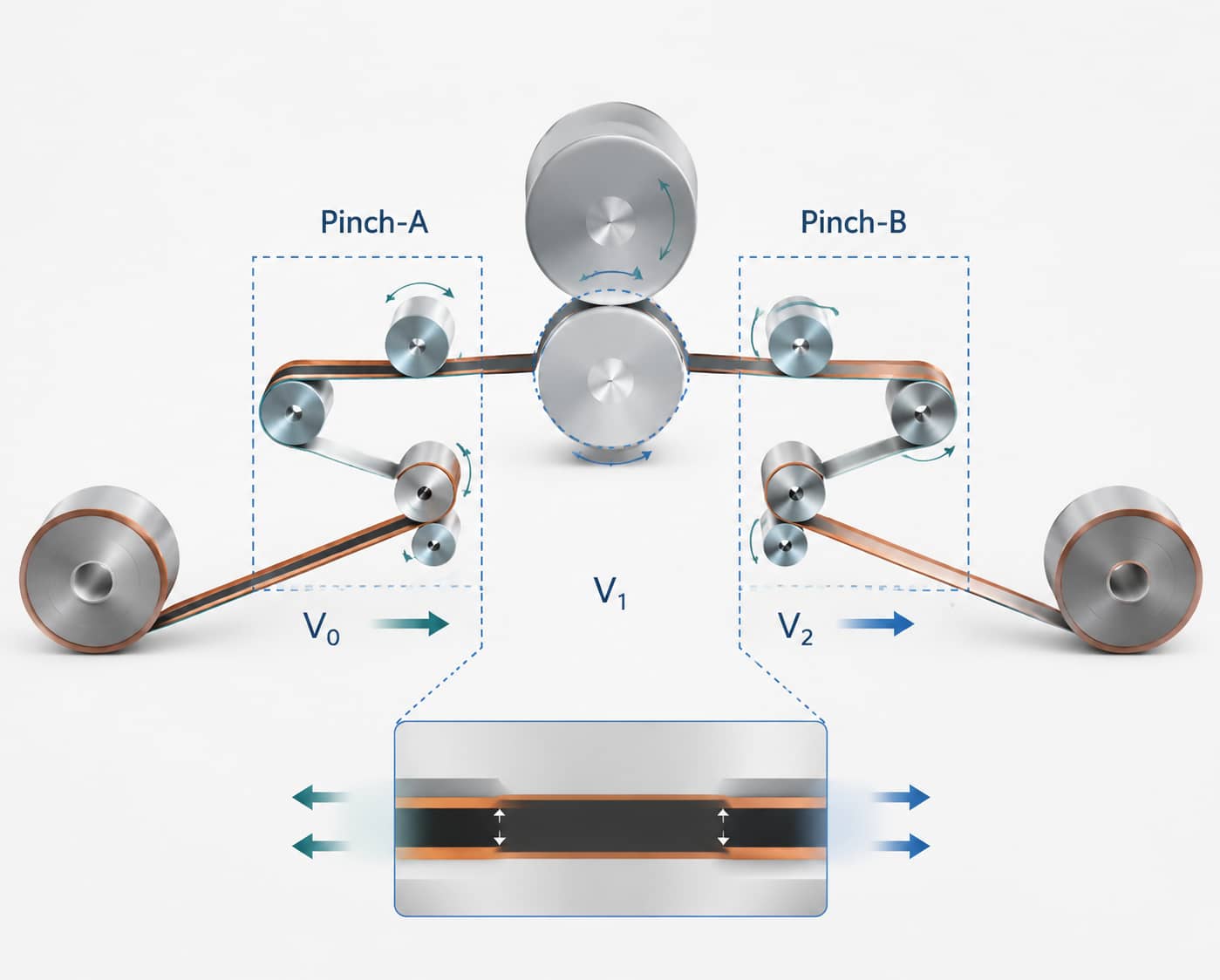
Simply put, Pinch differential tension technology actively stretches the bare foil area through a slight speed difference between two sets of pinch rolls, matching its length to that of the coated area and eliminating elongation differences at the source.
Specifically, one set of pinch rolls is installed before and after the rolling mill respectively. The front pinch roll (Pinch-A, speed V₀) is responsible for stable feeding and controlling the incoming strip speed, while the rear pinch roll (Pinch-B, speed V₂) is driven by a servo motor and rotates slightly faster than the front one, creating a subtle speed difference.
Critical Mechanical Limitation: A simple full-width speed difference cannot automatically stretch only bare foil. To concentrate corrective strain on uncoated margins, equipment must adopt segmented pinch sleeves, edge-localized traction rollers or customized web routing aligned with bare foil positions. Without targeted traction geometry, differential tension acts evenly across the full electrode width.
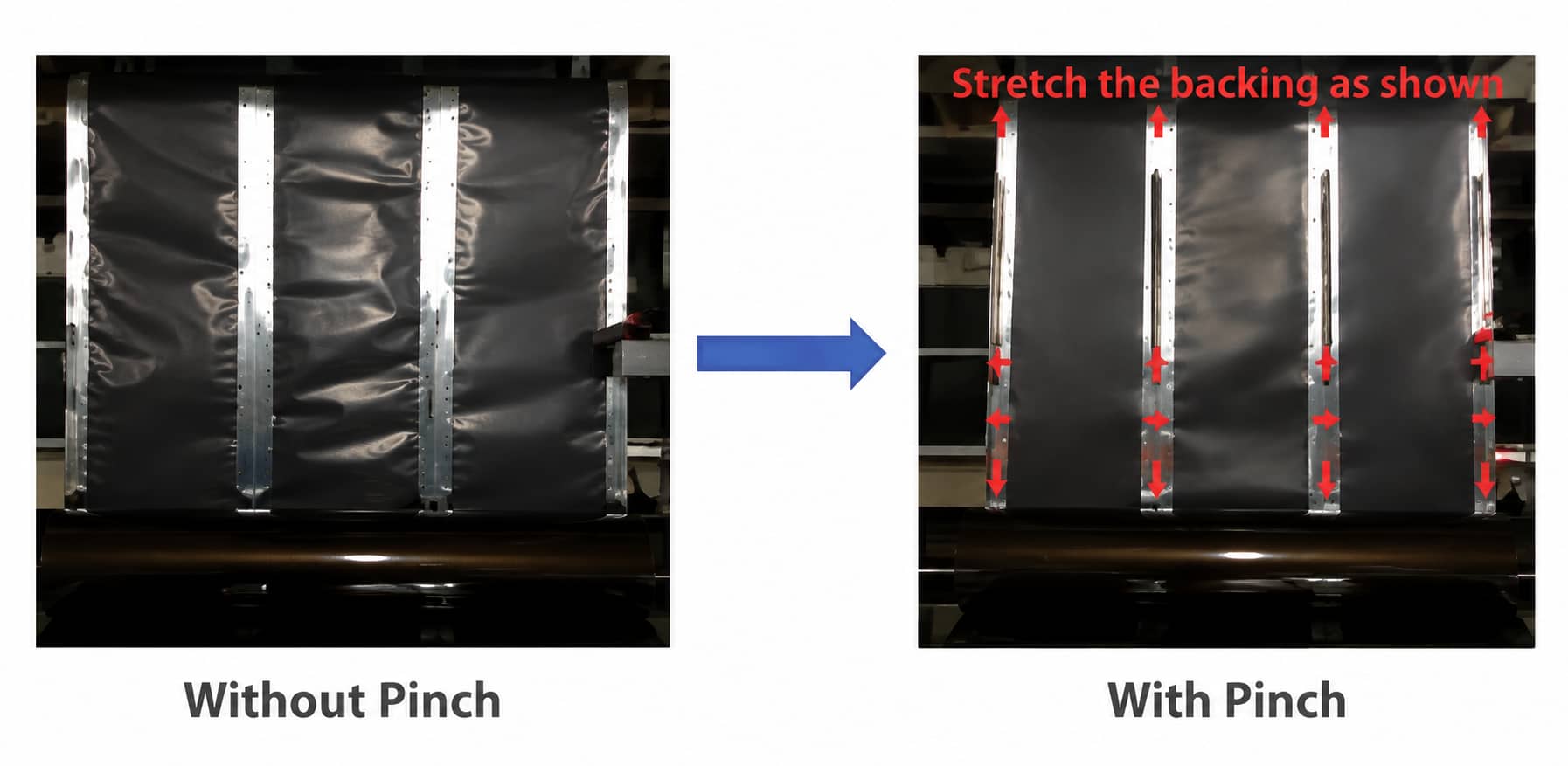
When the traction geometry is designed to concentrate corrective strain in the bare-foil lane, the bare region can experience greater additional elongation than the coated region. The actual strain distribution should be verified experimentally. Calendering changes the mechanical response of the coated composite region, and its post-nip strain and elastic recovery differ from those of the bare foil. The coated section will experience limited secondary elongation, while bare foil receives targeted stretching to balance length discrepancy.
5. Standard Protocol to Set Differential Tension Parameters
No universal fixed speed difference fits all electrode specifications. All adjustments must rely on measured strain data and multi-dimensional electrode integrity verification.
5.1 Key Variables That Adjust Required Compensation Magnitude
- Foil material & thickness: Thinner copper/aluminum foil is more sensitive to over-stretching
- Coating areal loading: Higher coating mass may widen strain gap under equal calender pressure
- Target compaction reduction rate: Larger thickness drop amplifies deformation discrepancy
- Production line speed: High operation speed delays servo tension response accuracy
- Coating adhesion strength: Low bonding tolerance restricts maximum allowable differential tension
5.2 Standard Longitudinal Strain Measurement Method
Use this formula to quantify the coated-bare strain gap before tuning pinch rolls:
ε = (L₁ - L₀) / L₀ × 100%
- Mark identical fixed gauge lengths on multiple transverse positions of coated and bare foil zones (align marks with machine direction)
- Measure original length L₀ under fully relaxed tension and constant ambient temperature before calendering
- Measure post-calender length L₁ after electrodes completely release tension stress
- Calculate average strain and data deviation from multi-point samples to eliminate cross-web thickness error
5.3 Safe Stepwise Debugging Flow
- Start with a small conservative differential setting as initial trial parameter
- Increase speed difference in tiny increments after each complete electrode coil run
- After each adjustment, inspect electrode flatness, coating integrity, thickness consistency and compaction density
- Lock the minimum differential value that visibly reduces wrinkles without inducing foil necking, coating cracks or powder shedding
Note: A 0.2%–0.8% differential speed range has been observed during internal production trials on specific electrode systems. This value can be adopted as an initial trial baseline, but thin foil or high-load coating sub-ranges cannot be generalized to all production lines without independent validation.
6. Pinch-Roll Tension vs Traditional Wrinkle Correction Methods
Compare mainstream industrial solutions for coated-bare strain mismatch defects, evaluating pros and cons for mass production:
| Correction Method | Core Working Principle | Main Advantages | Key Limitations |
|---|---|---|---|
| Pinch-Roll Differential Tension | Servo speed difference creates targeted bare foil stretching via customized traction geometry | Servo real-time adjustable, compatible with continuous high-speed lines, no recurring tape consumables | Requires high-precision servo control and dedicated bare foil traction structure |
| Temporary Tape Compensation | Paste gaskets on bare foil to balance roller gap pressure | Low technical threshold for small trial batches | Continuous adhesive tape cost, residual glue contamination, unstable correction precision, limits maximum line speed |
| Local Heating Softening | Heat bare foil locally to reduce tensile force required for stretching | Lower mechanical tension demand for ultra-fragile thin foil | Unstable thermal uniformity risk, easy coating thermal damage, extra heating energy cost |
| Reduced Calendering Reduction | Lower roller pressure to shrink coated-bare strain gap | No equipment modification needed | Sacrifices electrode compaction density and battery volumetric energy density |
Advantages of Pinch Differential Tension Technology
Compared with traditional solutions such as tape pasting for compensation rolling and local heating, this technology features three prominent advantages:
-
Precise and Controllable Effect: The speed difference is accurately adjusted via a servo system, and the stretching amplitude can be flexibly adjusted according to electrode materials and coating specifications. It is compatible with electrodes made of aluminum foil and copper foil of different thicknesses, solving various problems of uneven elongation.
-
Efficient Production without Consumables: It eliminates the need for pasting and stripping adhesive tapes, avoiding recurring consumable costs and the risk of residual adhesive contamination. The system can be integrated into continuous production, subject to equipment capability without mandatory reduction of line operating speed to meet high-speed rolling requirements.
-
Stable Quality Assurance: Only micro-stretching is applied to the bare foil area. Settings should be validated not to introduce coating cracks, powder shedding or foil necking, and the process should be checked to avoid altering electrode compaction density. With correct tuning, the technology helps minimise typical pole piece defects and improves process repeatability and electrode yield.
Balanced Evaluation: Pinch-roll differential tension is an established industrial approach for continuous roll-to-roll production, eliminating recurring tape consumable expense. Its correction precision and stability rely entirely on servo system accuracy and traction structural design; it cannot be labelled a universal all-defect optimal solution for all calendering wrinkle issues.
7. Troubleshooting: Wrinkles Persist After Pinch Tension Compensation
| Defect Phenomenon | Root Cause Analysis | Optimized Resolution |
|---|---|---|
| Bare foil remains wavy while coating surface is intact | Insufficient differential stretching applied to bare zones | Gradually raise rear pinch roll speed difference in small steps |
| Bare foil narrows and shows obvious necking deformation | Excessive corrective tension over-stretches thin foil | Immediately reduce servo speed difference and traction force |
| Fixed unilateral edge wrinkles after tension tuning | Calender rolls lack parallelism, transverse coating thickness imbalance | Calibrate roll parallelism first, then fine-tune differential tension |
| Whole electrode forms lateral bow (camber) | Uneven tension distribution across left/right web width | Optimize cross-web traction balance and web deviation correction parameters |
| Coating cracks appear after increasing pinch speed | Extra tension exceeds coating flexibility and interfacial adhesion | Lower differential tension; optimize upstream slurry mixing and drying process |
| Active powder shedding on calendered electrodes | Poor coating adhesion from defective slurry or over-compaction | Adjust binder proportion in battery slurry mixing process; optimize drying curve |
| Wrinkle defects worsen at elevated line speed | Servo tension response lag, minor roller slippage under dynamic load | Retune dynamic servo tension response parameters for high-speed operation |
8. Post-Compensation Process Validation Standards
A flatter electrode surface alone cannot confirm successful tension tuning; multi-dimensional performance verification is mandatory to avoid latent downstream defects.
- Physical dimension inspection: Electrode thickness consistency, transverse areal loading uniformity, compaction density stability
- Coating structural inspection: No cracks, powder shedding or delamination at coating-bare boundaries
- Electrochemical property test: Electrode sheet resistance, porosity, interfacial adhesion strength
- Downstream process simulation: Verify stable feeding in electrode slitting, tab welding and insulation taping, no winding stacking misalignment
Downstream Risk Reminder: Uncorrected electrode camber and bare foil wrinkles cause unstable slitting width, inconsistent tab welding positioning and pole piece offset during winding/stacking, raising assembly defect risks without directly damaging long-term battery cycle life. For full pouch cell manufacturing workflow, refer to lithium-ion pouch cell manufacturing process.
9. Frequently Asked Questions
Q1: What causes bare foil wrinkles after electrode calendering?
A1: The coated composite layer generates measurable longitudinal plastic deformation under calender compression, while uncoated bare foil produces far less strain. As an integrated continuous web, the length difference creates locked internal stress that releases as bare foil wrinkles or coating edge corrugations, often amplified by deflection roller contact under critical web tension.
Q2: Are all calendering wrinkles caused by coated-bare strain mismatch?
A2: No. Longitudinal waves, unilateral camber and full-width wrinkles mainly come from unstable web tension, misaligned calender rolls, uneven coating thickness or residual stress from drying. Strain mismatch only generates fixed-position bare foil boundary wrinkles.
Q3: Is there a universal fixed differential speed setting for pinch rolls?
A3: No universal standard value exists. The 0.2%–0.8% speed range is a trial baseline observed on specific CANRD production lines, which must be re-measured and adjusted for different foil thicknesses, coating layouts and machine traction structures.
Q4: Will excessive pinch differential tension trigger new electrode defects?
A4: Yes. Overly large speed differences lead to bare foil necking, coating boundary cracking, powder shedding and frequent electrode web breakage, permanently damaging electrode structural integrity.
Q5: Can pinch-roll tension fix coating cracking and powder shedding issues?
A5: No. These defects originate from defective slurry dispersion, unreasonable binder ratios, over-drying or excessive calender compression, which require optimization of upstream coating and slurry processes rather than tension adjustment.
Q6: Will calibrated pinch tension change electrode compaction density?
A6: When configured reasonably, differential tension only corrects longitudinal dimensional strain and does not materially alter electrode compaction density. Thickness, porosity and sheet resistance still need full testing after parameter tuning to rule out secondary influence.
Conclusion
Electrode wrinkling during calendering is a multi-factor composite defect, where coated-to-bare longitudinal strain mismatch acts as one important trigger for bare foil and coating-edge localized wrinkles, rather than the sole root cause of all calendering deformation.
Pinch-roll differential tension serves as a practical continuous-production corrective technology to narrow coated-bare length gaps via servo-controlled micro speed difference and targeted bare foil traction design. Compared with tape compensation and local heating correction, it cuts recurring consumable costs and maintains stable high line speed operation.
In mass production practice, this established technology delivers tangible improvements on eligible production lines. After properly adopting Pinch differential tension technology for strain-mismatch wrinkles, many production sites record a sharp reduction in electrode wrinkling and warping defect rates, fewer web breakage incidents, and removal of ongoing labor and tape costs required by the tape compensation workflow.
Standard production debugging workflow for engineers: Classify wrinkle types → Measure coated-bare strain mismatch → Judge pinch technology applicability → Apply conservative differential tension increments → Validate electrode structural integrity → Confirm stable performance in downstream slitting and winding processes. For lithium-ion battery manufacturers pursuing high-yield, high-precision electrode calendering, pinch-roll tension control is a reliable targeted solution for strain-mismatch bare foil wrinkles.
Previous
How Are Lithium-Ion ...Related Products & Services
Use Canrd products and R&D services to turn battery knowledge into practical experiments.
Coin Cell Case
ProductCoin cell cases for validating materials and electrochemical concepts from the article.
Use coin cell cases in your next test →Sodium Electrolyte
CategoryElectrolytes for sodium-ion battery research, compatibility tests, and cell validation.
Shop sodium electrolyte for validation →Cell Fabrication
ServiceGet support building dry cells, assembled cells, or custom formats for R&D validation.
Request cell fabrication support →Experimental Materials
CategoryBrowse materials for follow-up experiments, benchmarking, and product development.
Browse experimental battery materials →