contact@canrd.com
 +86 18928276992
 Home/Resources/Knowledge/Cell Fabrication/Battery Electrode Slitting Guide: How to Control Burrs Before Winding?
Battery Electrode Slitting Guide: How to Control Burrs Before Winding?
Canrd July 18, 2026 609
After the electrode coating, drying and roll pressing procedures, large-format positive and negative electrode mother rolls cannot be directly used for cell winding or lamination stacking. Three core pre-winding processes—electrode slitting, ultrasonic tab welding, and insulating green tape pasting—are mandatory to process wide electrode rolls into qualified narrow electrode strips with conductive tabs and edge insulation protection.
Slitting controls electrode edge burrs and dimensional precision; ultrasonic welding creates stable conductive connection between current collector foil and tabs; green tape coating isolates metal burrs and prevents internal short circuits. These three connected processes directly determine battery safety, internal resistance consistency and long-cycle stability, acting as critical transition procedures linking electrode rolling and winding/stacking.
1. Electrode Slitting Process Overview
1.1 Definition & Core Function
Electrode slitting is the procedure of cutting wide post-rolled electrode mother rolls into narrow electrode strips of fixed width via slitter blades, completing rewinding of small electrode rolls for subsequent welding and pasting. Core production goals:
- Unify the width tolerance of positive/negative electrode strips according to cell design drawings;
- Strictly control section burr and longitudinal edge burr size to eliminate piercing risks of separator film;
- Ensure neat electrode rewinding without wrinkling, deviation or material shedding.
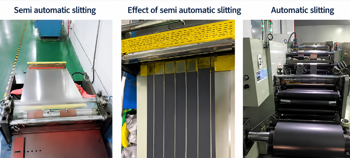
1.2 Slitting Equipment Classification & Application Scenarios
Three mainstream slitting equipment types are adopted across laboratories and mass-production battery factories, with distinct applicable scenarios:
-
Manual Cutting Machines: Mainly used in university laboratories and small R&D labs. Disadvantages include poor dimensional repeatability and uncontrollable electrode burr size, not applicable for mass production.
-
Semi-automatic Slitting Machines: Low investment cost, semi-manual feeding and rewinding, suitable for small-batch trial production of prototype cells.
- Automatic Slitting Machines: Fully automated unwinding, correction, slitting and rewinding, equipped with real-time CCD online inspection. Mass-production power/consumer battery factories primarily adopt this model for stable burr and width control.
1.3 Mandatory Critical Slitting Process Parameters
All must be locked before batch production:
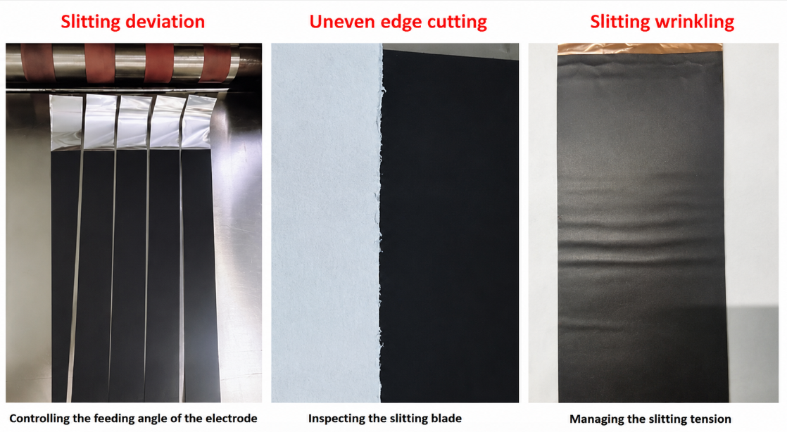
- Blade clearance & overlap: Incorrect overlap creates jagged edges and oversized burrs
- Line tension (unwind/rewind): Over-tension wrinkles electrodes; under-tension causes winding dislocation and width deviation
- Electrode feeding angle: Misaligned guide rollers lead to uneven edge cutting
- Rewinding speed mismatch: Speed differences generate strip offset during take-up
1.4 Common Slitting Defects, Hazards & Inspection Standards
Three fatal slitting defects frequently appear in mass production, all of which will trigger battery internal short circuit during winding:
-
Slitting width deviation: Electrode positive/negative overhang dimension exceeds design tolerance, causing lithium precipitation and capacity attenuation;
-
Uneven cutting edge: Jagged metal foil edges form sharp burrs;
- Slitting wrinkling: Continuous folds on electrode strip lead to local thickness abnormality after winding, triggering cell bulging.
1.4.1 Burr Testing Standard (Core Safety Index)
Burr size is the No.1 control index of slitting procedure, inspected via CCD microscopic observation:
- Acceptance criterion: Burr length ≤ 1/2 of separator film thickness;
- Risk of out-of-spec burr: Burrs pierce separator during winding, resulting in micro-short circuit, self-discharge surge and thermal runaway safety hazards.
1.4.2 Slitting Inspection Tools
- Measuring tools: 0.5mm precision stainless steel straightedge, spiral micrometer;
- Defect detection: CCD high-magnification observation system, optical projector.
2. Ultrasonic Tab Welding Process
After slitting, qualified narrow electrode strips enter the tab welding station to weld conductive metal tabs onto the exposed current collector foil of electrode tabs.
2.1 Welding Equipment & Working Principle
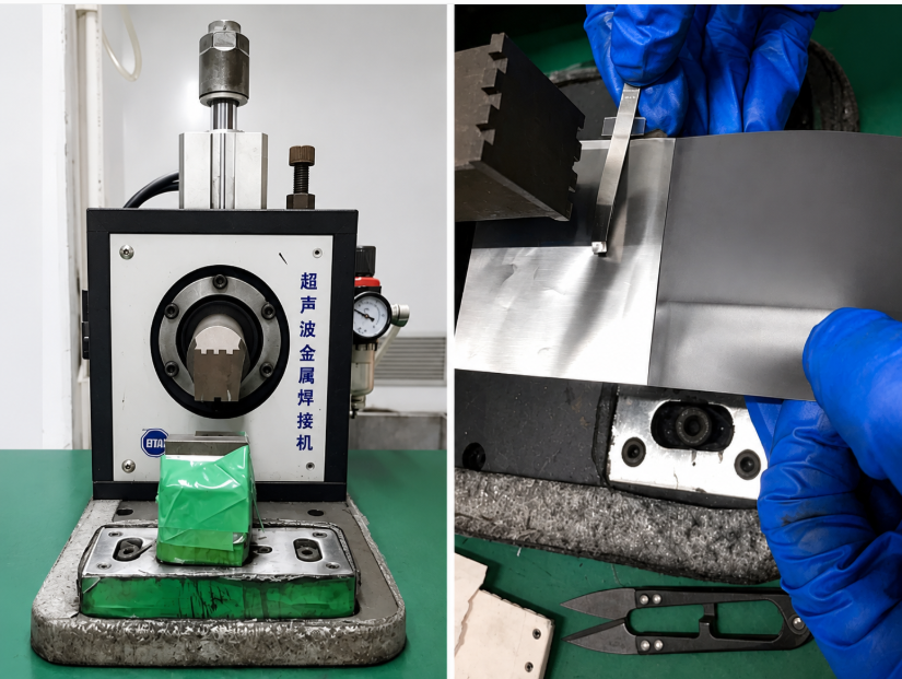
Mass production lines deploy ultrasonic metal welding machines as standard welding equipment, replacing resistance welding and laser welding for electrode-tab connection.
Working mechanism: High-frequency ultrasonic vibration generates instantaneous friction heat between tab metal and current collector foil, realizing cold metal fusion without melting auxiliary materials, avoiding electrode active material carbon shedding.
2.2 Positive/Negative Tab Material Matching Rules
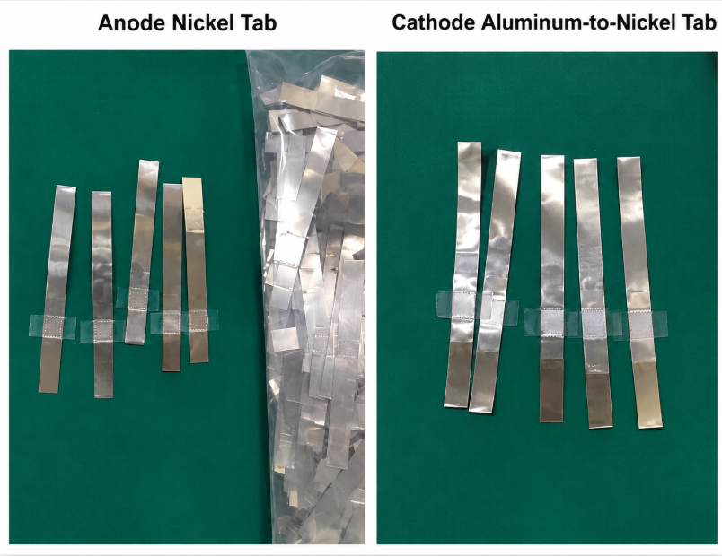
Strict tab material matching is specified for lithium-ion full cells to prevent electrochemical corrosion at welding joints:
-
Anode (negative electrode) tab: Pure nickel tab (Ni tab), matched with copper current collector foil of negative electrode;
- Cathode (positive electrode) tab: Aluminum-nickel composite tab (Al-Ni tab), matched with aluminum current collector foil of positive electrode;
2.3 Core Welding Control Indicators
- Welding tension between tab and current collector: Low tension leads to tab detachment during winding;
- Welding imprint appearance: Continuous, uniform welding points without foil penetration or perforation;
- Tab spacing consistency: Uniform tab position for unified tab center distance during winding inspection via X-ray testing.
2.4 Hidden Risks of Poor Welding
- Tab falling off during winding/stacking: Cell open circuit, zero discharge capacity;
- Over-welding penetration of current collector foil: Metal fragments fall off, forming internal conductive foreign matter;
- Uneven welding points: Local high internal resistance, severe heat generation during high-rate discharge.
3. Green Insulating Tape Coating (Gluing) Process
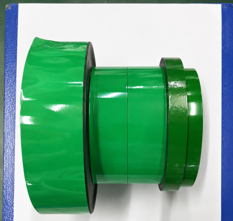
Tab welding is immediately followed by green tape pasting, also named edge insulation gluing, an indispensable anti-short-circuit protection procedure before winding.
3.1 Purpose of Green Tape Coating
Two core functional targets of special green high-temperature resistant tape pasting:
- Wrap exposed metal foil edges and welding burrs, preventing sharp metal from piercing separator film;
- Cover electrode cutting edges to suppress active material powder shedding during winding tension stretching.
3.2 Gluing Position Classification
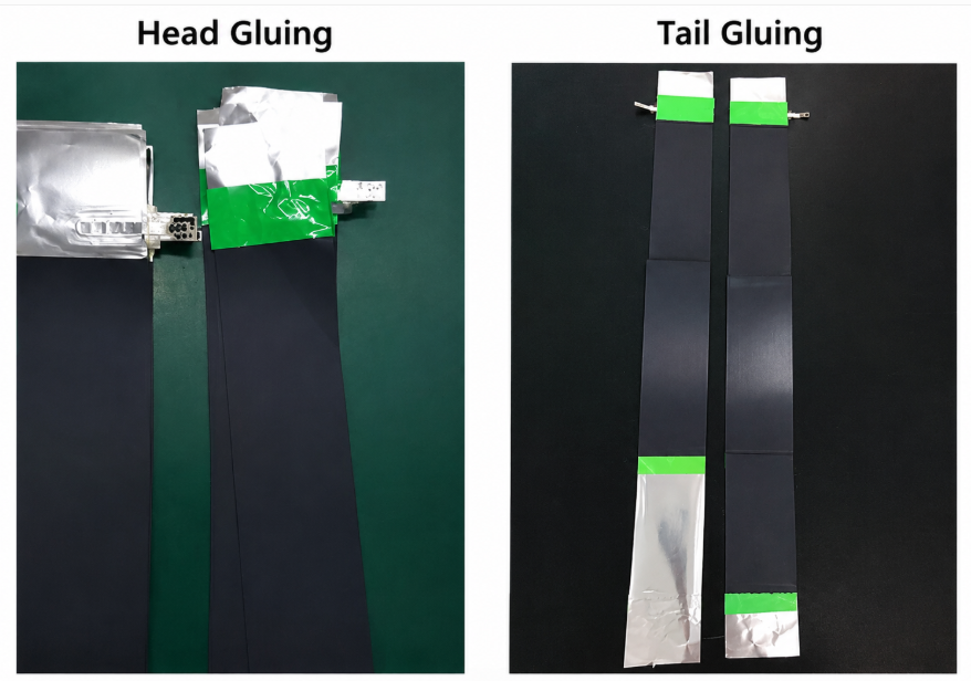
Two fixed tape pasting positions are set on each electrode strip:
- Head gluing: Insulate the welding joint between tab and current collector;
- Tail gluing: Protect the slitting cutting edge at the electrode strip tail.
3.3 Qualified vs Defective Gluing Standards
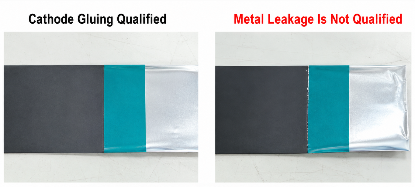
Qualified Cathode Gluing
Green tape completely covers the metal foil exposed area of electrode edge, no metal leakage, uniform tape edge without offset.
Disqualified Defect: Metal Leakage
Partial current collector foil exposed outside green tape; residual burrs on exposed metal cause separator puncture after winding.
3.4 Common Gluing Process Defects
- Tape offset: Green tape fails to fully wrap metal edge;
- Tape wrinkling/bubbling: Insulation layer falls off during winding;
- Insufficient tape width: Local metal leakage hidden at electrode head/tail.
4. Process Connection Between Slitting-Welding-Gluing and Front/Rear Procedures
4.1 Upstream Connection: Post Roll Pressing
Roll pressing homogenizes electrode compaction density and thickness; only electrodes with qualified rolling thickness can enter slitting. Over-compacted electrodes are prone to foil cracking during slitting, while under-compacted electrodes suffer severe powder shedding during welding vibration.
4.2 Downstream Connection: Pre Winding & Stacking
All electrodes after slitting, welding and gluing must pass pre-winding appearance inspection before cell forming; unqualified electrodes with burrs, tab detachment or metal leakage are eliminated to avoid batch defective bare cells.
4.2.1 Pre-Winding Electrode Inspection Items
- Electrode fracture, surface damage, indentation defects;
- Active material decarbonization and current collector metal exposure;
- Green tape falling off, metal leakage at glued positions.
4.2.2 Winding Failure Caused by Unqualified Gluing Electrodes
The most typical winding defect induced by poor gluing: Negative electrode strip fails to fully cover the green tape area of positive electrode, electrode tail overflows outside insulation tape. Uncovered metal burrs scratch separator film during layered winding, forming micro-short circuits inside bare cells.
5. Mass Production Operation Safety Specifications
Slitter, ultrasonic welding machine and gluing machine all have mandatory safety operation rules to prevent mechanical injury:
- Slitting machine: Strictly prohibit touching blades and blade holders during equipment operation;
- Ultrasonic welder: Keep fingers away from tab feeding and welding pressure head areas;
- Automatic gluing machine: Do not reach into tape traction and electrode conveying rollers;
- All equipment must be locked and powered off during blade replacement, mold maintenance and defect clearing.
6. Core Testing Tools for The Three Processes
| Process | Dedicated Testing Tools | Testing Purpose |
|---|---|---|
| Slitting | CCD microscope, stainless steel straightedge, projector | Burr measurement, electrode width detection |
| Tab Welding | Welding tension tester | Verify tab-foil bonding strength |
| Green Tape Gluing | Spiral micrometer, visual magnifier | Check tape coverage width, metal leakage |
Advantages of Standardized Slitting-Welding-Gluing Process
- Improve battery safety: Effectively eliminate separator puncture short-circuit risks induced by electrode burrs;
- Stabilize cell electrical performance: Uniform welding joints reduce single-cell internal resistance difference;
- Lower production scrap rate: Standard tape pasting reduces winding defective cell proportion;
- Extend battery cycle life: Suppress active material shedding during long-term winding compression.
Limitations of Improper Process Control
- Excessive slitting burrs: High self-discharge rate, thermal runaway risk;
- Unstable ultrasonic welding: Large internal resistance fluctuation, abnormal heat generation during discharge;
- Green tape metal leakage: Batch micro-short circuits, finished cell capacity rapid attenuation.
Frequently Asked Questions
Q1: Why is burr control the top priority of electrode slitting?
Metal burrs longer than half the separator thickness pierce isolation film during winding, creating permanent micro short circuits, elevated self-discharge and thermal runaway safety hazards.
Q2: What is electrode overhang, and how does slitting affect it?
Electrode overhang refers to the 1–3mm dimensional offset designed so negative electrodes fully wrap positive electrodes to prevent lithium plating. Slitting width deviation breaks this offset standard. For full winding overhang control rules, read our dedicated winding & stacking guide.
Q3: What’s the difference between head gluing and tail gluing?
Head gluing insulates tab weld joints to stop cross-contact between positive/negative metal tabs; tail gluing seals slitting cut edge burrs at the electrode strip end to prevent separator scratching during winding layers.
Q4: Why do mass factories use ultrasonic welding instead of laser welding for tabs?
Ultrasonic cold fusion avoids high-temperature heat damage to electrode active material, eliminates powder shedding at welds, and maintains stable bonding strength under long-term winding tension.
Q5: What advantages do automatic tabbing lines hold over semi-manual welding equipment?
Integrated welding gluing inline processing, consistent tab spacing for X-ray inspection, inline pull testing and higher continuous production throughput for large battery orders.
Conclusion
Electrode slitting, ultrasonic tab welding and green insulating tape coating are three interconnected pre-forming core processes between electrode rolling and cell winding/stacking. Precise control of slitting burr size, tab welding tension and green tape coverage directly determines the safety consistency, electrical performance and cycle lifespan of finished lithium-ion full cells.
Mass production factories must configure full-automatic slitting lines with online CCD detection, standard ultrasonic welding equipment and automatic gluing machines, with strict 100% pre-winding appearance inspection to eliminate defective electrodes from entering the winding station. Mastering the defect generation mechanism and control standards of these three procedures is essential for reducing production scrap rate and improving lithium battery product quality.
Previous
Battery Electrode Ca...Related Products & Services
Use Canrd products and R&D services to turn battery knowledge into practical experiments.
Coin Cell Case
ProductCoin cell cases for validating materials and electrochemical concepts from the article.
Use coin cell cases in your next test →Sodium Electrolyte
CategoryElectrolytes for sodium-ion battery research, compatibility tests, and cell validation.
Shop sodium electrolyte for validation →Cell Fabrication
ServiceGet support building dry cells, assembled cells, or custom formats for R&D validation.
Request cell fabrication support →Experimental Materials
CategoryBrowse materials for follow-up experiments, benchmarking, and product development.
Browse experimental battery materials →