contact@canrd.com
 +86 18928276992
 Home/Resources/Knowledge/Cell Fabrication/Lithium-Ion Battery Formation Process: SEI, Gas Generation and Pouch Cell Swelling Troubleshooting
Lithium-Ion Battery Formation Process: SEI, Gas Generation and Pouch Cell Swelling Troubleshooting
Canrd July 30, 2026 343
Introduction
Lithium-ion battery formation is the mandatory initialization procedure implemented after electrolyte filling and sufficient cell resting. All frontline cell R&D engineers, production supervisors and quality inspectors frequently encounter formation-related failures including pouch swelling, elevated internal resistance, low initial coulombic efficiency and inconsistent batch performance.
1. Rapid Reference Table for Abnormal Formation Defects
| Observed Cell Defect | Priority Inspection Items |
|---|---|
| Excessive gas yield during formation charging | Raw material moisture content, electrolyte solvent ratio, formation current ramp, fixture heating temperature |
| Visible pouch swelling before degassing | Normal first-charge side reactions, insufficient airbag reserved volume, uneven electrode contact gap |
| Continuous thickening after secondary sealing | Unstable incomplete SEI layer, residual trapped gas, moisture contamination inside cell |
| Low initial coulombic efficiency | Excessive irreversible lithium consumption, high graphite specific surface area, low-voltage sustained side reactions |
| Sharply increased internal resistance post formation | Inadequate electrode pre-wetting, insufficient clamping pressure, over-thick SEI, sluggish charge transfer reaction |
| Wide capacity & OCV deviation within one batch | Uneven fixture pressure, inconsistent electrolyte injection, temperature difference between formation channels |
| Rapid OCV drop after aging storage | Severe interface instability, internal micro-shortage, persistent electrolyte reduction reactions |
2. What Is Lithium-Ion Battery Formation?
Formation refers to the activation process of cathode and anode active materials after electrolyte injection and full cell resting, realized through standardized charge-discharge cycles. The core product of formation is the Solid Electrolyte Interphase (SEI) film grown on anode particle surfaces.
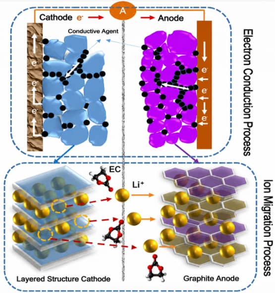
Formation is the initialization step for lithium-ion cells, and the formation of SEI film is its most critical core content. The SEI film forms on graphite anode surfaces during the first charge when lithium ions deintercalate from cathode materials and migrate to the anode.
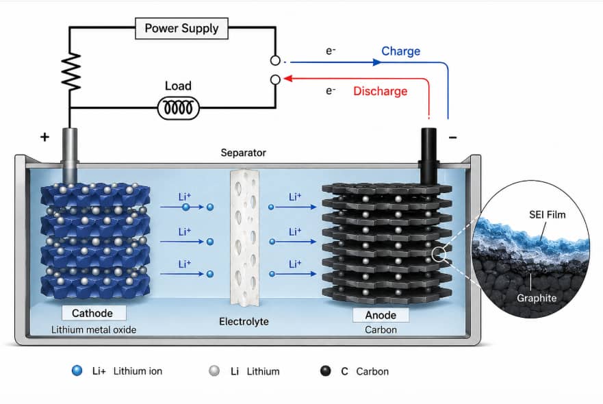
Advantages of qualified SEI films
Stabilize electrode active substances and block continuous irreversible reduction reactions between electrolyte and active particles, directly determining cell capacity, rate performance, cycle life and high/low temperature performance.
Drawbacks brought by SEI film
- Consumes part of active lithium inside the cell, requiring extra cathode material loading to compensate irreversible lithium loss during the first charge;
- Increases electrode-electrolyte interfacial resistance and brings obvious voltage hysteresis during charge and discharge.
Note: Thin passivation film can also form on cathode surfaces, but its electrochemical influence is far weaker than anode SEI, so all subsequent SEI mentioned in this article refers to the anode interphase film.
3. Why Do Lithium Cells Generate Gas During Formation?
Gas is an inevitable byproduct of irreversible electrolyte reduction reactions in the first charge. This chapter adopts the test data from Canrd 1300mAh LCO/graphite pouch cell experiment: Test cell configuration: 1300mAh capacity, 4.2V lithium cobalt oxide cathode, synthetic graphite anode, PP separator, 1mol/L LiPF6 EC:DMC:EMC=1:1:1 electrolyte, test method: water displacement gas measurement GC-MS gas component analysis, charging rate 0.02C with gradient cutoff voltages.
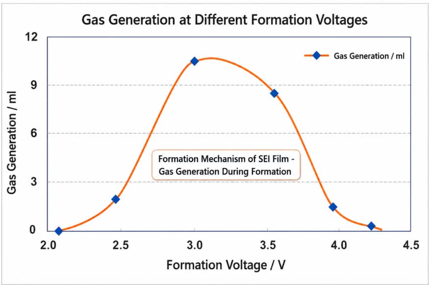
3.1 Total gas volume change rule
- 2.0V–2.5V: Extremely low gas output, only trace water & lithium salt hydrolysis reactions occur, no obvious SEI film-forming reaction;
- 3.0V–3.5V: Gas generation reaches the peak value, EC cyclic carbonate decomposes violently, which is the core voltage window for SEI generation;
- Above 3.5V: Complete SEI coverage suppresses EC reduction, total gas volume drops rapidly;
- Above 3.8V: Linear carbonate DMC and EMC become the main decomposition objects, generating useless alkane gas with no contribution to SEI protection.
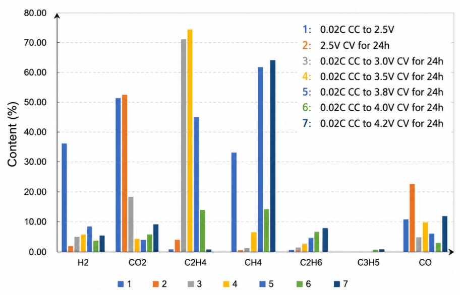
3.2 Gas component classification by voltage interval
- Low voltage (<2.5V): Main gases H₂, CO₂, and CO are produced by side reactions involving trace moisture hydrolysis;
- Medium voltage (3.0V~3.5V): Main gas CO₂, C₂H₄; ethylene is the characteristic product of EC decomposition and effective SEI generation;
- High voltage (>3.8 V): Main gases are CH₄, C₂H₄, C₂H₆, C₃H₈, and CO—alkane byproducts resulting from the decomposition of linear carbonates.
3.3 Core chemical reactions generating gas
Main reversible cell reactions
Cathode delithiation: LiCoO2 → Li1-xCoO2 + xLi+ + x e-
Anode lithiation: 6C + xLi⁺ + xe⁻ = LiₓC₆
Full-cell overall reaction:LiCoO2 6C = Li1-xCoO2 LixC6
Low-voltage impurity side reactions (below 2.5V)
- H2O + e- = OH- + 1/2H2(g)
- OH-Li = LiOH(s)
- LiOH Li e- = Li2O(s) 1/2H2(g)
- LiPF6 = LiF PF5
- PF5 H2O = 2HF PF3O
- 2HF Li2CO3 = LiF H2CO3
- H2CO3 = H2O CO2(g)
EC solvent film-forming & gas-producing reaction
- EC e- = EC·(EC free radical)
- 2EC· 2Li = CH2=CH2(g) (CH2OCO2Li)2(s)
- EC 2Li 2e- = CH3OLi(s) CO(g)
DMC & EMC linear carbonate side reactions
- DMC e-Li = CH3OCO2Li(s)CH3·
- CH3· 1/2H2 = CH4(g)
- EMC e-Li = CH3OCO2Li(s) C2H5·
- C2H5· 1/2H2 = C2H6(g)
All gas products generated in formation include H₂, CO, CO₂, C₂H₄, CH₄, C₂H₆, so temporary airbags must be reserved for all pouch cells to store gas generated during the first charge.
4. Why Does a Pouch Cell Swell After Formation?
Pouch swelling is the most intuitive failure phenomenon in formation workshops, which can be divided into four root cause categories:
- Normal first-charge side reaction swelling Within the 3.0–3.5V optimal SEI window, EC decomposition will inevitably produce gas. If the airbag volume is designed according to the benchmark gas yield, the thickness will recover to normal after complete degassing.
- Excessive abnormal side reaction swelling When raw material moisture exceeds the standard, electrolyte formula is mismatched or formation cutoff voltage is lower than 3.0V, solvent continuous decomposition will generate far more gas than the control group.
- Swelling caused by insufficient degassing Inadequate vacuum degree or short holding time in the degassing station leads to residual gas trapped inside the cell stack, forming mild bulges after secondary sealing.
- Long-term swelling after sealing The SEI film formed in formation is discontinuous and incomplete. Electrolyte keeps contacting graphite particles, triggering sustained decomposition and slow gas accumulation during storage.
Symptom comparison table for swelling judgment
| Swelling performance | Corresponding root cause | Recommended verification method |
|---|---|---|
| Swell during formation, stable after degassing | Nominal SEI gas generation | Compare airbag volume design with benchmark gas data |
| Gas volume far higher than standard batches | Moisture pollution or defective electrolyte | GC-MS gas composition test raw material moisture detection |
| Thin bulge remains after secondary sealing | Incomplete vacuum degassing | Adjust degassing vacuum and holding time |
| Cell thickens gradually after long-term storage | Discontinuous protective SEI layer | EIS batch screening accelerated aging test |
| Uniform thickness rise with little gas detected | Graphite lithium intercalation expansion | Check formation target SOC and fixture pressure |
5. How Does the SEI Film Grow During the First Charge?
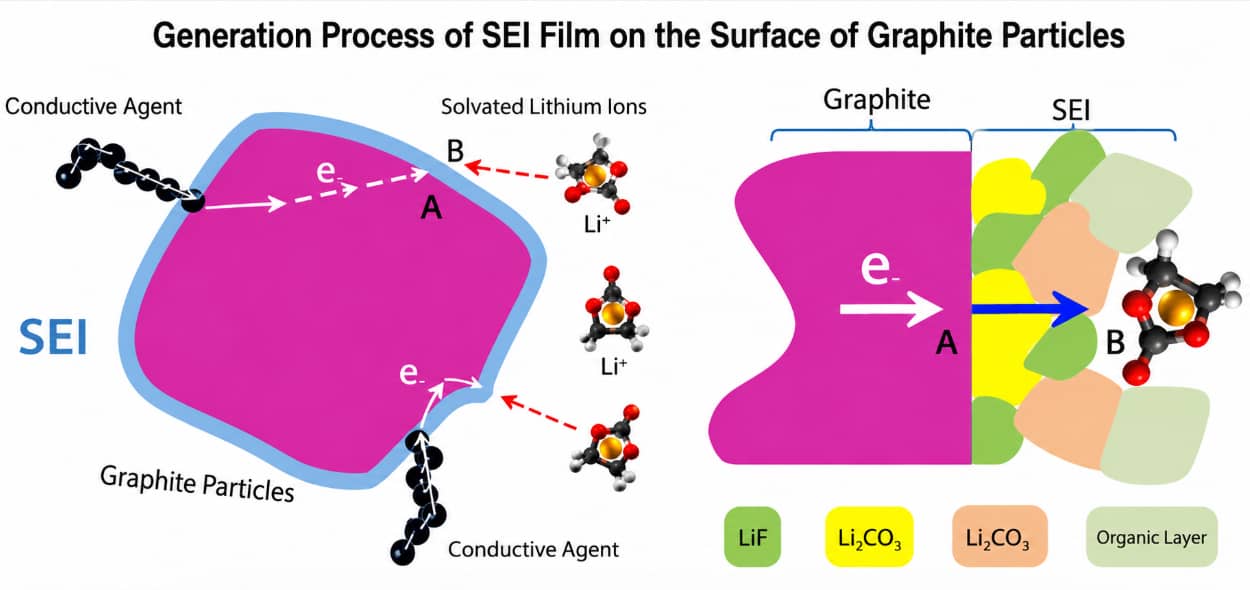
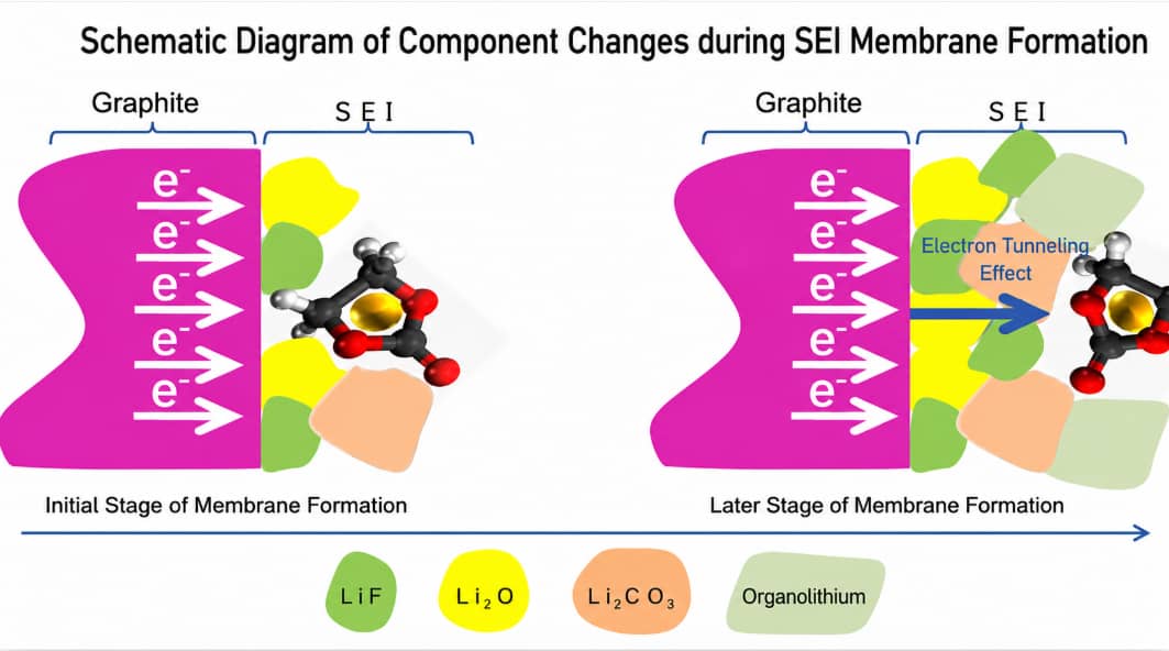
5.1 Four-step dynamic SEI generation mechanism
- Electron transmission: Electrons flow from copper current collector through conductive agent and aggregate at Point A inside graphite particles;
- Solvated lithium ion diffusion: Lithium ions wrapped by solvent molecules diffuse from cathode to Point B on the surface of existing SEI;
- Electron tunneling transmission: SEI is an electronic insulator, electrons can only pass through thin interphase via quantum tunneling effect to reach outer reaction Point B;
- Interfacial reduction precipitation: Tunneled electrons react with lithium salt, solvent and film-forming additives to precipitate new inorganic & organic lithium compounds, continuously thickening SEI until graphite surface is fully covered.
5.2 Layered inorganic-organic compositional gradient of SEI
Two types of reduction reactions coexist during formation, creating a non-uniform layered structure along SEI thickness direction:
- Early formation stage (near graphite substrate): High electron density on bare graphite surface triggers two-electron reactions, producing inorganic components LiF, Li₂O, Li₂CO₃, LiOH as the main inner layer substances with high stability and low ion resistance;
- Late formation stage (electrolyte side): Electrons need to tunnel through pre-formed SEI, electron concentration decreases sharply, single-electron radical reactions dominate to generate flexible organic lithium salts (ROCO₂Li, ROLi) forming the outer layer.
Before 3.5V, alkyl lithium carbonate and Li₂CO₃ are the main SEI components; after exceeding 3.5V, alkyl lithium carbonate and alkoxylithium become dominant substances.
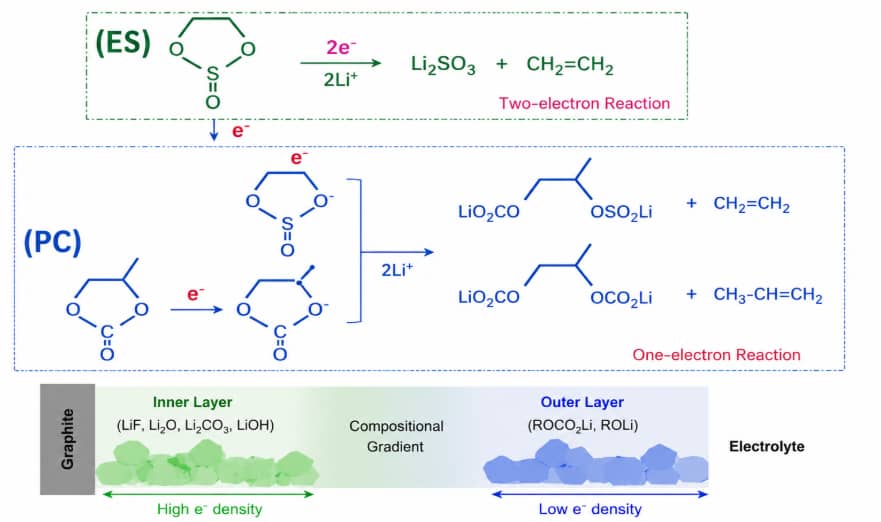
Two-electron reactions tend to generate inorganic lithium salt components, while one-electron reactions mostly produce organic lithium salts. This rule is verified by PC solvent ES additive electrolyte system test.
5.3 Why SEI cannot grow infinitely
The core limiting factor is electron tunneling distance. Electrons can only pass through ultra-thin insulating media. Once SEI thickness exceeds the critical tunneling limit, almost no electrons can reach the outer film surface to drive reduction reactions, and SEI growth naturally stops.
Special exception: Silicon-carbon anode particles produce severe volume expansion during cycling, repeatedly tearing the SEI barrier, which will trigger unlimited repeated growth of interphase film and continuous rise of internal resistance.
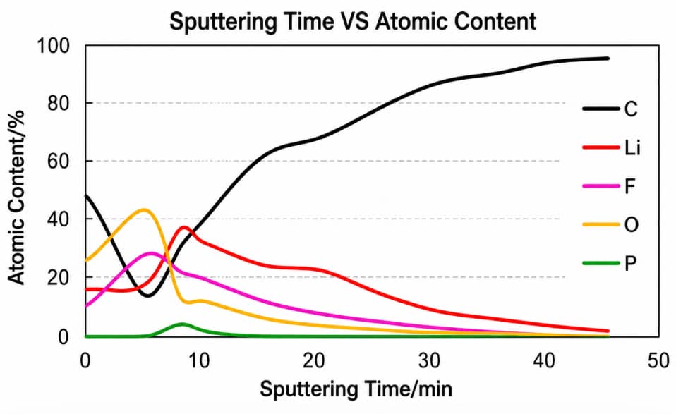
5.4 Anisotropic SEI thickness on graphite crystal planes
Argon ion sputtering XPS depth profiling test on highly oriented graphite shows obvious thickness difference:
- End plane (main lithium intercalation channel): SEI thickness ~30nm, requiring thick protective film to resist solvent erosion during frequent ion embedding;
- Base plane (low lithium activity): SEI thickness only ~2nm, with negligible side reactions.
6. Why Is Initial Coulombic Efficiency Low After Formation?
Low first-cycle efficiency originates from irreversible lithium loss in SEI forming reactions. Lithium ions extracted from cathode participate in irreversible reduction and are fixed inside solid inorganic/organic SEI precipitates, unable to return to cathode during discharge, forming permanent irreversible capacity loss.
Moderate lithium consumption is necessary to build protective SEI. Excessively low ICE usually corresponds to the following process defects:
- Excessively high graphite specific surface area provides massive side reaction sites;
- Formation cutoff voltage lower than 3.0V leads to incomplete SEI and sustained solvent decomposition in later cycles;
- Excessive trace moisture in electrolyte and separations accelerates hydrolysis side reactions;
- Over-high formation current density causes uncontrolled violent reduction reactions.
Optimization direction: Calibrate cutoff voltage within the system-specific 3.0–3.5V window, strictly control raw material moisture index, and reduce the current of Step 1 SEI forming stage.
7. Why Does High Internal Resistance Appear Post-Formation?
Four major root causes of increased cell resistance after formation:
- Over-thick dense SEI film: Excessive formation current or temperature accelerates rapid interphase precipitation, forming an ion-blocking barrier and raising RSEI;
- Inadequate pre-formation wetting: Dry electrode pores cannot be fully filled by electrolyte, increasing bulk solution resistance Rs;
- Insufficient formation fixture pressure: Uneven cathode-anode gaps break the continuous conductive network and expand charge transfer resistance Rct;
- Over-abundant organic outer SEI: Long low-current holding time thickens the flexible organic outer layer and slows solid-phase lithium diffusion.
Engineers can distinguish different resistance abnormalities via EIS spectrum testing.
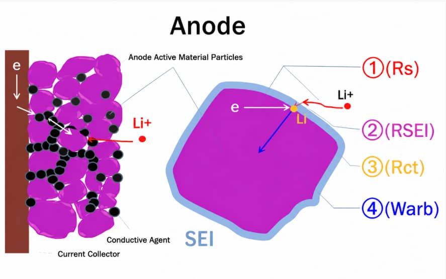
8. What Can EIS Spectra Reflect About Formation Quality?
8.1 Five lithium intercalation steps matched with EIS parameters
- Electron transmission inside electrodes & free lithium ion migration in electrolyte (corresponds to Rs solution resistance);
- Lithium ion penetration through SEI film (corresponds to RSEI SEI resistance, CSEI interphase capacitance);
- Electron-lithium ion charge transfer redox reaction (corresponds to Rct charge transfer resistance, Cdl double-layer capacitance);
- Solid-state lithium atom diffusion inside graphite particles (corresponds to Warburg diffusion impedance);
- Lithium accumulation changes graphite crystal structure (corresponds to Rb bulk resistance, Cb bulk capacitance, Cint intercalation capacitance).
8.2 EIS application limitations in production
EIS is a non-destructive batch screening tool for comparing differences between cell batches, but it cannot independently confirm absolute SEI thickness, chemical composition or single-variable root causes. Temperature, SOC, cell resting time and contact pressure will all interfere with EIS curve shapes. XPS sputtering and GC-MS are required for accurate surface composition analysis.
9. Key Formation Process Control Variables
The two core factors determining SEI composition are electron density at the reaction interface and reactant concentration in electrolyte. All adjustable parameters that affect these two indicators include formation current, clamping pressure, heating temperature, electrolyte formula and cutoff voltage.
Detailed single-factor test data, pouch cell & coin cell standardized process windows and dQ/dV cutoff potential calibration methods are fully elaborated in the follow-up article: Lithium-Ion Battery Formation Parameters: Current, Pressure, Temperature, SOC and Cutoff Voltage.
10. Standardized Troubleshooting Workflow for Abnormal Formation Batches
- Symptom classification: Divide failures into gas/swelling defects, low ICE defects, high resistance defects and poor batch consistency defects;
- Control group comparison: Test abnormal cells with identical raw material, cell design and electrolyte formula as qualified control samples;
- Multi-dimensional data cross-check: Collect formation voltage curve, dQ/dV differential capacity, total gas yield, post-formation thickness and full EIS spectrum data for comprehensive analysis;
- Single-variable verification: Only adjust one formation parameter per batch test to avoid overlapping interference of multiple variables;
- Full-process traceability: Link formation records with upstream electrolyte filling and downstream degassing & sealing data to distinguish inherent formation side reactions and post-processing defects.
Frequently Asked Questions
Q1 What is the essential difference between formation charging and conventional charge-discharge?
Formation charging triggers one-time irreversible electrolyte reduction to form protective SEI film, which only occurs on newly filled cells for the first charge. Conventional cycling only realizes reversible lithium intercalation without sustained side reactions.
Q2 Why does SEI formation consume active lithium and reduce initial efficiency?
Lithium ions extracted from cathode participate in irreversible reduction and are fixed inside solid SEI precipitates, unable to return to cathode during discharge, producing irreversible capacity loss.
Q3 Why must pouch cells reserve airbags during formation?
SEI forming side reactions inevitably produce gaseous byproducts. Airbags reserve expansion space to prevent pouch deformation and electrode delamination, and all gas will be removed via vacuum degassing before permanent secondary sealing.
Q4 How does insufficient fixture pressure affect SEI uniformity?
Low pressure creates uneven cathode-anode gaps. Narrow gaps carry high current density to form over-thick SEI, while wide gaps generate discontinuous thin interphase, leading to large cell-to-cell performance deviation.
Q5 Can EIS testing replace XPS to analyze SEI composition?
No. EIS only reflects macroscopic electrochemical impedance response, while XPS realizes direct surface element and composition detection. The two characterization tools are complementary and cannot substitute each other.
Conclusion
Lithium-ion battery formation is targeted electrode-electrolyte interface modification rather than simple pre-charging. All common production failures including swelling, high resistance and low initial efficiency are derived from abnormal SEI growth and voltage-dependent electrolyte decomposition reactions.
Key takeaways for process optimization:
- The 3.0–3.5V voltage window corresponds to the most active EC decomposition and SEI generation in LCO/graphite systems, and this range needs re-verification for other battery chemistries;
- SEI presents an inorganic inner layer and organic outer layered structure, with quantum electron tunneling effect limiting its unlimited thickening;
- EIS can quickly screen batch consistency but must be combined with XPS, GC-MS and other characterization means to accurately judge SEI thickness and composition;
- All adjustable formation parameter windows are detailed in the dedicated formation parameter article for process design reference.
Previous
Solve Electrode Cale...Related Products & Services
Use Canrd products and R&D services to turn battery knowledge into practical experiments.
Coin Cell Case
ProductCoin cell cases for validating materials and electrochemical concepts from the article.
Use coin cell cases in your next test →Sodium Electrolyte
CategoryElectrolytes for sodium-ion battery research, compatibility tests, and cell validation.
Shop sodium electrolyte for validation →Cell Fabrication
ServiceGet support building dry cells, assembled cells, or custom formats for R&D validation.
Request cell fabrication support →Experimental Materials
CategoryBrowse materials for follow-up experiments, benchmarking, and product development.
Browse experimental battery materials →