contact@canrd.com
 +86 18928276992
 Solve Electrode Calendering Elongation Mismatch: Pinch Differential Speed Tension Technology
Introduction
Electrode calendering is one of the most critical processes in lithium-ion battery manufacturing. By compressing coated electrodes between precision rollers, manufacturers control electrode thickness, compaction density, porosity, and dimensional consistency—parameters that directly influence battery energy density, cycle life, rate capability, and manufacturing stability. In addition to improving electrochemical performance, a stable calendering process is essential for ensuring consistent quality during downstream operations such as slitting, winding, stacking, and cell assembly.
As lithium-ion batteries continue evolving toward higher energy density, faster charging capability, and lower manufacturing costs, battery manufacturers are increasingly adopting ultra-thin current collectors, higher compaction densities, and high-speed continuous production lines. Before discussing differential elongation, it is important to understand the fundamentals of the electrode calendering process. Our previous article, Lithium Electrode Calendering Guide: Compaction Density Standards, explains how compaction density, rolling pressure, porosity, and electrode thickness influence battery performance and manufacturing quality. Understanding these fundamentals provides valuable context for the elongation control strategies discussed in this article. Lithium Electrode Calendering Guide: Compaction Density Standards
One of the most common yet frequently overlooked problems is non-uniform elongation between the coated electrode region and the uncoated foil area. During calendering, different regions of the electrode undergo different levels of plastic deformation, resulting in inconsistent elongation along the strip. The resulting residual stress gradually accumulates throughout the production process and eventually appears as wavy edges, wrinkles, edge curling, strip wandering, or even strip breakage. As production speeds continue to increase, these defects become increasingly difficult to control and have become one of the major challenges limiting production yield and manufacturing efficiency.
Many production lines attempt to reduce these defects through higher rolling precision, tension adjustment, adhesive tape compensation, or localized heating. Although these approaches may alleviate symptoms under certain operating conditions, they do not fundamentally eliminate the difference in elongation between the coated and uncoated regions. Consequently, process stability remains highly dependent on operator experience and frequent parameter adjustments.
This article focuses on the formation mechanism of differential elongation during electrode calendering and explains why it has become a critical challenge for modern lithium-ion battery manufacturing. More importantly, it introduces Pinch Differential Speed Tension Technology, an industrial solution that actively compensates for elongation through precisely controlled differential-speed pinch rolls. By synchronizing the final length of both coated and uncoated regions, this technology effectively eliminates residual stress, significantly improves electrode flatness, and provides a practical upgrade path for both new and existing calendering production lines.
Why Does Differential Elongation Occur During Electrode Calendering?
Electrode Structure Determines Different Mechanical Behavior
To understand why differential elongation occurs, it is first necessary to examine the structure of a lithium-ion battery electrode.
Whether manufacturing cathodes or anodes, the finished electrode is generally divided into two functional regions:
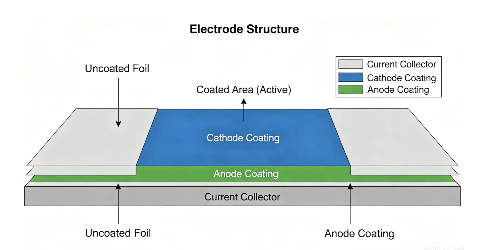
- Coated Area– The current collector is coated with active material, conductive additives, and binder. This region stores lithium ions and determines the electrochemical performance of the battery.
- Uncoated Foil Area (Tab Area)– A narrow strip of exposed copper or aluminum foil reserved for current collection and tab welding during cell assembly.
Although both regions are part of the same continuous electrode, their mechanical behavior during calendering differs considerably because of their structural differences.
The coated area consists of multiple material layers with significantly greater thickness than the bare foil. During rolling, the coating is compressed together with the current collector, causing both the coating and the metal foil to deform under substantial compressive force. In contrast, the uncoated foil contains only the metallic current collector and experiences a much lower effective rolling load. Consequently, the two regions do not undergo identical deformation even though they pass through the same calendering equipment.
This difference in deformation behavior forms the foundation of differential elongation.
Plastic Deformation of the Coated Area
During calendering, the coated electrode passes through the gap between two precision rollers operating under carefully controlled pressure.
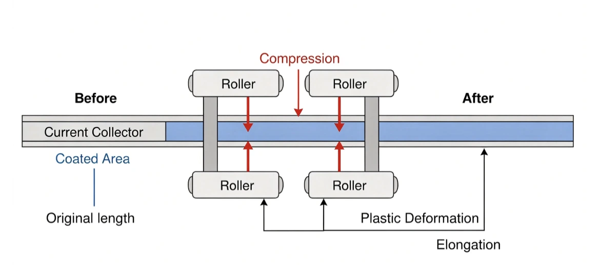
The primary objective of this process is to:
- Increase compaction density
- Reduce electrode thickness
- Improve particle contact
- Optimize porosity
- Enhance volumetric energy density
However, calendering affects more than just the coating itself.
As rolling pressure increases, the metallic current collector beneath the coating also experiences plastic deformation. Once the applied stress exceeds the material's yield strength, the foil no longer deforms elastically. Instead, it undergoes permanent plastic deformation, resulting in a slight increase in its longitudinal length.
Although the elongation of the coated region is relatively small—typically measured in fractions of a percent—it is sufficient to create dimensional inconsistency across the entire electrode strip. The exact elongation depends on multiple manufacturing parameters, including:
- Copper or aluminum foil thickness
- Coating loading
- Compaction density
- Rolling pressure
- Roller gap
- Electrode speed
- Mechanical properties of the current collector
As manufacturers continue reducing foil thickness to achieve higher energy density, the current collector becomes more susceptible to plastic deformation, making elongation control increasingly important.
Why the Uncoated Foil Barely Elongates
Unlike the coated region, the uncoated foil area behaves very differently during calendering.
Since no active material is present, this section does not experience the same compressive loading generated by coating densification. The rolling force acting on the bare foil is significantly lower, and in many cases the stress never reaches the yield strength required for permanent plastic deformation.
As a result, the uncoated region maintains nearly its original length after passing through the calender.
This seemingly small difference creates a significant mismatch between adjacent regions of the same electrode strip:
- Coated Area:Undergoes plastic deformation and becomes slightly longer.
- Uncoated Foil Area:Experiences little or no permanent elongation.
Image
Although the absolute difference in length may only be a few tenths of a percent, the accumulated mismatch across hundreds of meters of continuous electrode generates substantial residual stress. Under high-speed production conditions, this stress cannot be fully released in a controlled manner. Instead, it gradually manifests as dimensional instability, eventually producing defects such as wavy edges, wrinkles, strip wandering, and strip breakage.
In other words, many of the quality issues observed after calendering do not originate from inadequate rolling pressure or insufficient compaction density. Rather, they arise because different regions of the same electrode are forced to coexist despite having different final lengths.
Understanding this differential elongation mechanism is therefore the first step toward identifying an effective engineering solution. Rather than simply modifying rolling pressure or introducing local compensation measures, manufacturers must address the elongation mismatch itself. This is precisely the objective of Pinch Differential Speed Tension Technology, which will be discussed in the next section.
How Differential Elongation Leads to Electrode Defects
Differential elongation may appear insignificant from a numerical perspective, but its impact on electrode quality becomes increasingly pronounced during continuous production. A difference of only 0.2-0.8 percent in elongation between the coated and uncoated regions is sufficient to generate residual stress across the electrode strip. As production speeds increase and electrode widths become larger, this stress accumulates over hundreds of meters, eventually resulting in visible defects that compromise both product quality and manufacturing efficiency.
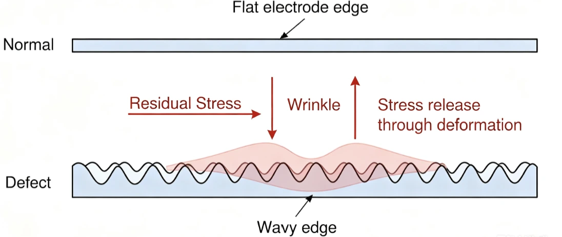
Unlike isolated process variations, differential elongation affects the entire electrode continuously. Because the coated region becomes longer while the uncoated foil remains almost unchanged, both regions are forced to travel together despite having different natural lengths. The resulting stress is gradually released through deformation of the electrode strip.
Wavy Edges
Wavy edges are the most common symptom of differential elongation.
When the coated area elongates more than the adjacent uncoated foil, the excess length cannot be accommodated uniformly. Instead, the electrode edges buckle outward to release the accumulated stress, producing a periodic wave-like profile.
Although waviness may initially appear minor, it directly affects downstream web handling. Uneven edges make accurate guiding more difficult during slitting and winding, increasing the likelihood of alignment errors and reducing production stability.
For ultra-thin current collectors, even slight waviness can become unacceptable because dimensional tolerances are considerably tighter than in conventional electrode manufacturing.
Wrinkles and Edge Curling
As residual stress continues to accumulate, localized deformation becomes more severe.
Instead of forming gentle waves, portions of the electrode begin to wrinkle or curl, particularly near the transition between coated and uncoated regions. These defects are often irreversible because they result from permanent plastic deformation rather than temporary elastic bending.
Wrinkled electrodes are difficult to transport through downstream equipment and frequently lead to:
- Poor web tracking
- Uneven winding tension
- Reduced stacking accuracy
- Increased rejection rates
More importantly, wrinkles may locally damage the coating, creating defects that cannot be corrected in later manufacturing stages.
Strip Wandering and Strip Breakage
In high-speed calendering lines, differential elongation also affects strip stability.
Because internal stress is distributed unevenly across the electrode width, the strip may gradually deviate from its intended path, resulting in strip wandering. Operators often compensate by repeatedly adjusting web guides or tension settings, but these corrections treat only the symptoms rather than the underlying cause.
When production speed, rolling pressure, or web tension increases further, the accumulated stress may eventually exceed the mechanical strength of the current collector. The result is strip breakage, one of the most costly failures in continuous electrode production.
A single strip breakage typically requires operators to stop the production line, reconnect the electrode, recalibrate web tension, and restart the equipment. The resulting downtime reduces equipment utilization and increases production costs.
Downstream Impact on Cell Manufacturing
The influence of differential elongation does not end after calendering.
Electrodes with poor dimensional stability continue to create problems during:
- Slitting
- Notching
- Winding
- Stacking
- Cell assembly
For example, wavy edges can reduce slitting accuracy, while curled electrodes may produce uneven winding layers that ultimately affect cell consistency and assembly yield.
Consequently, eliminating differential elongation is not merely a quality improvement for the calendering process—it is a prerequisite for maintaining stable production throughout the entire lithium-ion battery manufacturing line.
Conventional Solutions and Their Limitations
Because differential elongation has long been recognized as a common manufacturing challenge, various compensation methods have been adopted across the lithium-ion battery industry. Among them, adhesive tape compensation and localized heating are the two most widely used approaches.
Although these methods can reduce certain defects under specific operating conditions, they do not fundamentally eliminate the difference in elongation between the coated and uncoated regions. As electrode specifications continue to evolve toward thinner current collectors and higher production speeds, their limitations have become increasingly apparent.
Adhesive Tape Compensation
Adhesive tape compensation has been used in many calendering lines because of its relatively simple implementation.
The basic principle is to apply protective tape to the uncoated foil before calendering. By locally increasing the thickness of the bare foil, the rolling conditions are partially modified, reducing the difference in deformation between coated and uncoated regions.
While this method can improve flatness under certain conditions, it introduces several disadvantages.
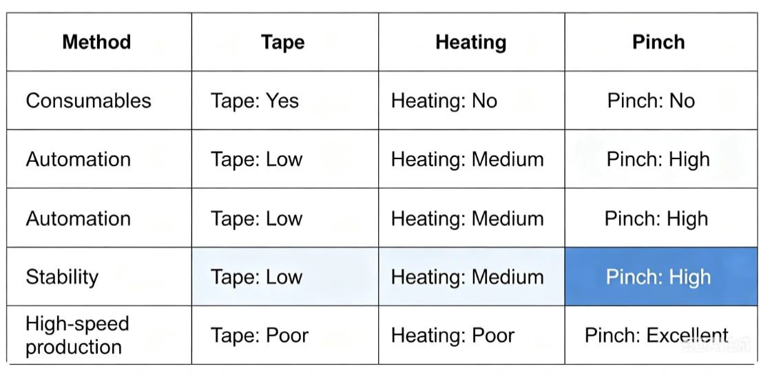
First, adhesive tape is a consumable material, resulting in continuous operating costs throughout production.
Second, applying and removing the tape requires additional manual operations or dedicated automation equipment, increasing both labor requirements and process complexity.
Third, adhesive residue may remain on the current collector after tape removal. Even trace contamination can interfere with subsequent welding processes or introduce quality risks for high-performance lithium-ion batteries.
Most importantly, adhesive tape compensation does not actually control elongation. Instead, it merely changes the local rolling conditions in an attempt to reduce the resulting dimensional difference. Consequently, process stability remains highly dependent on operating experience and frequent parameter adjustments.
Localized Heating
Another commonly adopted approach is localized heating of the uncoated foil.
Heating temporarily lowers the yield strength of the metal foil, making it easier for the uncoated region to elongate during calendering. In theory, this additional deformation can partially compensate for the elongation generated in the coated region.
However, precise temperature control is extremely challenging during continuous high-speed production.
Excessive heating may influence the physical properties of nearby electrode materials, while insufficient heating provides little improvement. Furthermore, integrating heating equipment into existing calendering lines increases system complexity, energy consumption, and maintenance requirements.
For modern high-speed production lines operating at several hundred meters per minute, maintaining consistent temperature distribution across the electrode width becomes particularly difficult.
As a result, localized heating is generally unsuitable for large-scale continuous manufacturing where repeatability and process stability are critical.
Why Conventional Methods Cannot Eliminate the Root Cause
Although adhesive tape compensation and localized heating approach the problem from different directions, they share the same fundamental limitation.
Both methods attempt to modify the rolling conditions, rather than directly controlling the final elongation of the electrode.
In other words, they seek to influence deformation indirectly instead of ensuring that the coated and uncoated regions reach the same final length after calendering.
This distinction is crucial.
As electrode specifications become more diverse, the optimal compensation also changes with foil thickness, coating loading, compaction density, rolling pressure, and production speed. Conventional methods therefore require repeated trial-and-error adjustments and often struggle to maintain stable performance across different products.
What manufacturers truly need is not another passive compensation technique, but an active and precisely controllable system capable of adjusting elongation in real time.
This requirement has led to the development of Pinch Differential Speed Tension Technology. Rather than altering the rolling process itself, the technology introduces a carefully controlled differential speed between servo-driven pinch rolls after calendering, actively stretching only the uncoated foil until its elongation matches that of the coated region. By directly compensating for the elongation mismatch, the technology addresses the root cause of waviness, wrinkles, edge curling, and strip breakage instead of merely mitigating their symptoms.
Pinch Differential Speed Tension Technology
Unlike conventional compensation methods that attempt to modify rolling conditions, Pinch Differential Speed Tension Technology directly addresses the root cause of differential elongation by actively controlling web tension after calendering.
The core concept is straightforward: instead of trying to reduce the elongation of the coated region, the technology introduces a precisely controlled micro-elongation to the uncoated foil area. Once both regions reach nearly identical final lengths, the residual stress responsible for waviness, wrinkles, and strip breakage is effectively eliminated.
Because the compensation is achieved through servo-controlled differential speed rather than additional rolling force or thermal treatment, the process is highly repeatable, digitally adjustable, and fully compatible with modern high-speed electrode production lines.
System Configuration
A typical Pinch Differential Speed Tension system consists of three primary sections:
- Front Pinch Roll Unit
- Calender Mill
- Rear Pinch Roll Unit
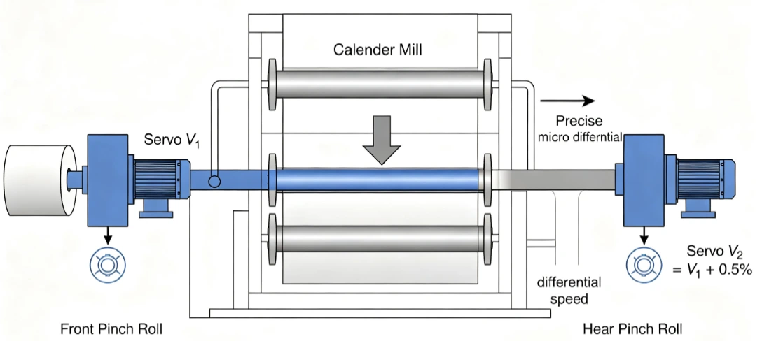
The front pinch roll is installed upstream of the calender and is responsible for stabilizing the incoming electrode strip. Driven by a servo motor, it establishes the reference web speed entering the rolling gap while maintaining stable web alignment and tension.
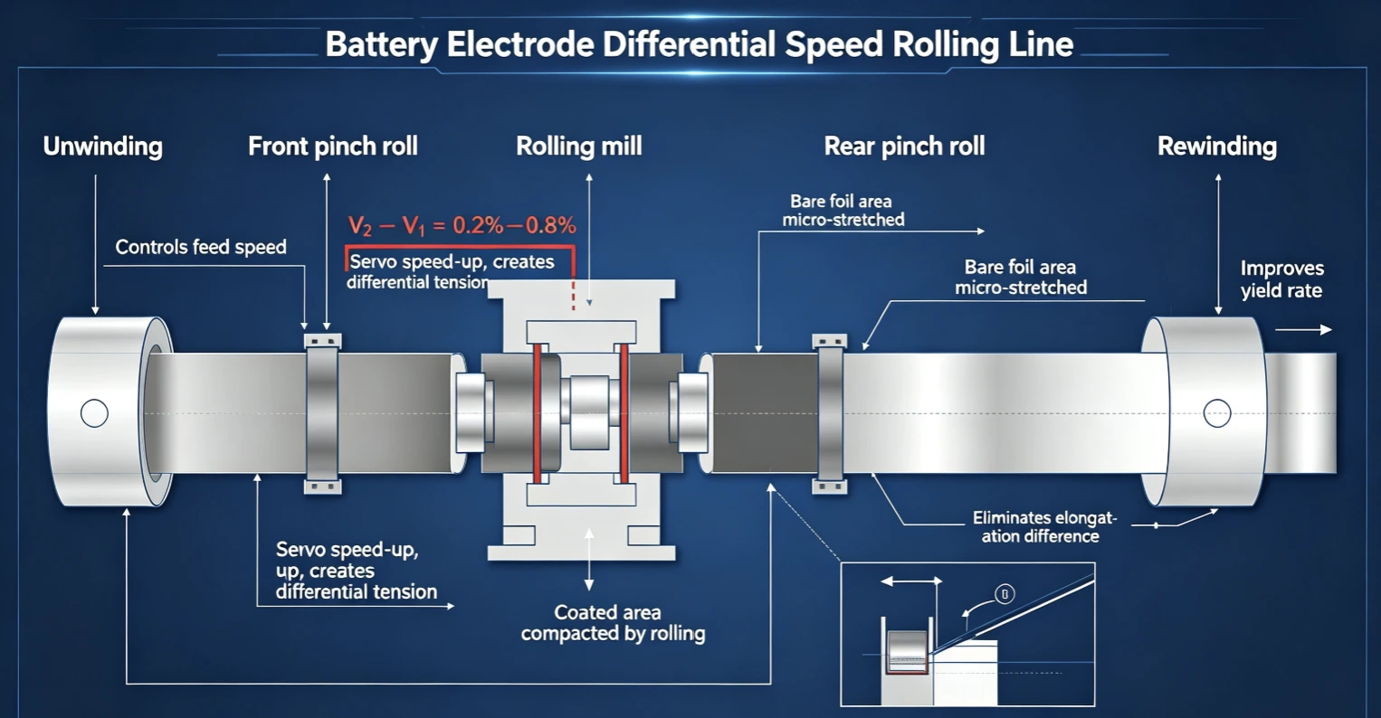
After the electrode passes through the calender, it enters the rear pinch roll unit. Unlike the front unit, the rear pinch roll operates independently and is controlled by a dedicated servo drive. Its speed is intentionally set slightly higher than the front pinch roll, typically by 0.2% to 0.8%, creating a precisely controlled differential speed.
Although the speed difference appears extremely small, it is sufficient to generate the tensile force required to compensate for the elongation mismatch without introducing excessive stress into the electrode.
This modular configuration allows the Pinch system to be integrated into existing calendering lines without modifying the rolling mill itself, making it an attractive retrofit solution for manufacturers seeking higher product quality with minimal equipment changes.
Working Principle
The effectiveness of Pinch Differential Speed Tension Technology lies in its selective compensation mechanism.
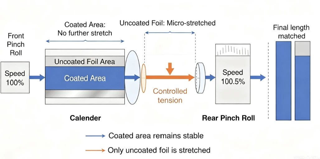
After calendering, the coated region has already undergone significant plastic deformation. As the coating becomes denser, the composite structure formed by the active material and current collector exhibits higher stiffness and an increased resistance to further deformation. Under the small differential tension generated by the pinch rolls, this region experiences virtually no additional elongation.
The uncoated foil behaves differently.
Since it has not been subjected to substantial rolling deformation, the bare copper or aluminum foil retains greater ductility. When exposed to the controlled differential speed between the front and rear pinch rolls, the uncoated region undergoes a slight and carefully controlled tensile deformation.
This process effectively increases the length of the uncoated foil until it matches the elongation of the coated section.
As a result:
- The coated area maintains its designed compaction density and thickness.
- The uncoated foil is stretched by only a very small amount.
- The final lengths of both regions become nearly identical.
- Residual stress across the electrode is significantly reduced.
Unlike conventional methods, compensation occurs after calendering and acts directly on the source of dimensional inconsistency rather than indirectly modifying the rolling process.
Why Only the Uncoated Foil Is Stretched
A common question raised by process engineers is why the coated region is not stretched together with the uncoated foil when differential tension is applied.
The answer lies in the difference in mechanical properties after calendering.
The coated region has already been densified under high rolling pressure. During this process, both the coating layer and the underlying current collector undergo plastic deformation, resulting in increased structural stiffness and a higher resistance to additional elongation.
In contrast, the uncoated foil has experienced little permanent deformation and therefore retains much of its original ductility.
When the differential speed reaches the preset value, the tensile force naturally concentrates in the softer uncoated region rather than the densified coated section. Consequently, only the uncoated foil undergoes micro-elongation, while the coated region remains dimensionally stable.
This selective deformation mechanism is the key reason why Pinch technology can compensate for elongation without affecting electrode thickness, compaction density, or coating integrity.
Servo Closed-loop Tension Control
The performance of the Pinch system depends on accurate and stable tension control.
Modern systems employ a fully digital closed-loop architecture consisting of:
- Servo motors
- High-resolution rotary encoders
- PLC-based motion control
- Real-time speed synchronization
- Tension monitoring and feedback
The front pinch roll establishes the reference speed, while the rear pinch roll continuously adjusts its rotational speed according to the programmed differential ratio.
Encoder feedback allows the controller to monitor web movement in real time and automatically compensate for speed fluctuations, ensuring that the preset differential speed remains constant throughout production.
This closed-loop strategy offers several important advantages:
- Stable tension regardless of line speed fluctuations
- High repeatability between production batches
- Automatic compensation for process disturbances
- Reduced dependence on operator experience
Because all parameters are digitally controlled, manufacturers can establish optimized process recipes for different products and switch between them quickly without mechanical adjustments.
Parameter Optimization
Although the principle of differential-speed compensation is straightforward, selecting the appropriate speed difference is essential for achieving optimal performance.
In industrial production, the differential speed is typically maintained within the range of 0.2% to 0.8%.
The optimal value depends on several process variables, including:
- Copper foil thickness
- Aluminum foil thickness
- Coating loading
- Compaction density
- Rolling pressure
- Electrode width
- Line speed
- Material mechanical properties
For example, electrodes manufactured with ultra-thin 6 μm copper foil generally require more precise differential-speed control than those using thicker current collectors because thinner foils are more susceptible to deformation.
Likewise, electrodes with higher compaction densities often exhibit greater elongation differences, requiring correspondingly larger compensation.
Rather than relying on empirical adjustments, modern production lines can establish standardized parameter libraries for different electrode specifications. Operators simply select the appropriate production recipe, and the control system automatically applies the corresponding differential-speed settings.
This digital approach significantly improves process repeatability while reducing setup time during product changeovers.
Technical Advantages
Compared with conventional compensation methods, Pinch Differential Speed Tension Technology offers several important engineering advantages.
Higher Process Stability
Because elongation is actively controlled rather than indirectly influenced, compensation remains consistent across different production speeds and product specifications. The process is less sensitive to operator adjustments and provides excellent repeatability for long-term continuous manufacturing.
No Consumable Materials
Unlike adhesive tape compensation, the Pinch system requires no disposable materials.
This eliminates the cost of consumables while avoiding problems associated with adhesive residue, contamination, and additional cleaning processes.
No Thermal Influence
Since the technology relies entirely on mechanical tension control, it introduces no thermal effects.
Electrode coatings, binders, and active materials remain unaffected, ensuring that the designed electrochemical properties are fully preserved.
Compatible with High-speed Production
Servo-controlled differential speed can be maintained even on modern high-speed calendering lines operating at several hundred meters per minute.
Because compensation occurs continuously during production, the technology supports fully automated manufacturing without reducing line speed.
Easy Retrofit for Existing Production Lines
Perhaps one of the greatest advantages is that the Pinch system functions as a modular tension-control unit rather than a modification of the rolling mill itself.
Manufacturers can install the front and rear pinch roll assemblies on existing calendering equipment with relatively limited mechanical modifications, reducing both implementation cost and production downtime.
This modular design provides an attractive upgrade path for battery manufacturers seeking improved electrode quality without replacing major equipment.
Industrial Validation
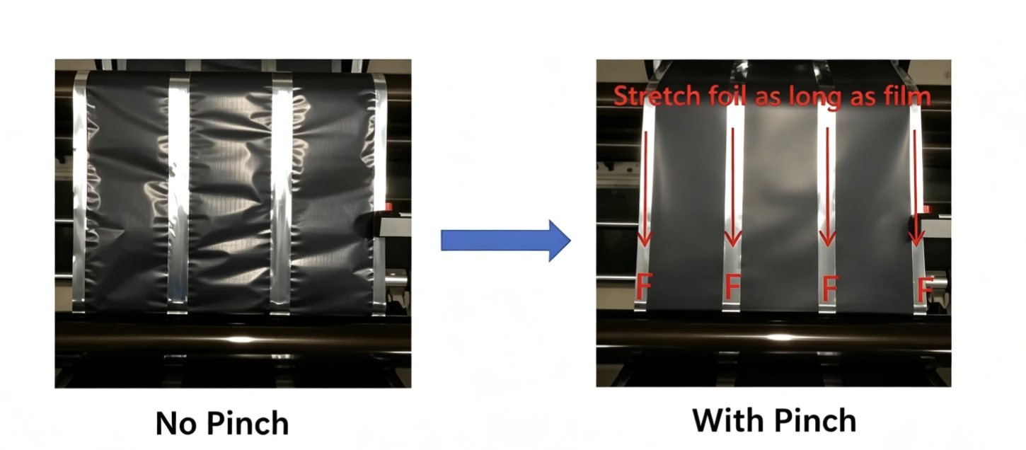
Pinch Differential Speed Tension Technology has been successfully implemented in commercial lithium-ion battery production lines and validated across a wide range of electrode specifications. From conventional EV batteries to next-generation ultra-thin current collectors, industrial applications consistently demonstrate that active elongation compensation is significantly more effective than passive correction methods.
Unlike laboratory verification, large-scale manufacturing places much higher demands on process stability. Continuous operation over hundreds or even thousands of meters requires every section of the electrode to maintain consistent dimensional accuracy. Even a slight mismatch in elongation can accumulate into substantial residual stress, eventually causing quality defects and unexpected production interruptions.
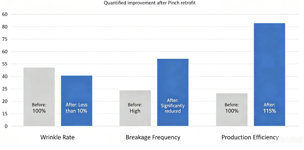
Field applications show that introducing servo-controlled differential-speed pinch rolls effectively equalizes the final length of the coated and uncoated regions, resulting in measurable improvements in both product quality and production efficiency.
Typical production improvements include:
- More than 90% reductionin wrinkles, waviness, and edge curling
- Significant reductionin strip breakage and unexpected line stoppages
- Complete eliminationof adhesive tape compensation
- Approximately 15% improvementin overall calendering line productivity
- Improved dimensional consistency for downstream slitting, winding, and stacking processes
- Reduced operator intervention through digital recipe management
Beyond these quantitative improvements, manufacturers also report more stable process capability (Cp/Cpk), fewer product changeover adjustments, and higher overall equipment effectiveness (OEE). Because the compensation parameters are digitally stored, production recipes can be reused with excellent repeatability, minimizing dependence on operator experience.
For battery manufacturers pursuing intelligent manufacturing and Industry 4.0 initiatives, these advantages extend beyond quality improvement. Stable electrode dimensions simplify process standardization, facilitate data-driven optimization, and support closed-loop manufacturing systems.
Typical Applications
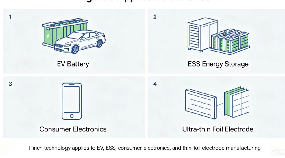
Although initially developed to address differential elongation during lithium-ion battery electrode calendering, Pinch Differential Speed Tension Technology is applicable to a wide range of battery manufacturing scenarios.
Power Battery Manufacturing
Power batteries demand high production efficiency, excellent dimensional consistency, and reliable continuous operation.
Modern EV battery production lines typically operate at high web speeds while using increasingly thinner current collectors. Under these conditions, differential elongation becomes more pronounced, making active tension compensation particularly valuable.
Pinch technology helps maintain stable electrode geometry, reducing defects before slitting and winding while improving overall production yield.
Energy Storage Batteries
Large-format energy storage batteries require long electrode strips with excellent flatness.
Because electrode lengths are substantially greater than those used in consumer electronics, residual stress has more opportunity to accumulate during production. Eliminating elongation mismatch significantly improves web stability throughout continuous manufacturing.
Consumer Electronics Batteries
Although consumer batteries are generally smaller, they often require extremely tight dimensional tolerances.
Any electrode waviness or edge deformation may influence stacking precision and ultimately affect cell consistency. Differential-speed tension control provides an effective solution without compromising production efficiency.
Ultra-Thin Current Collectors
One of the most promising application areas is the production of electrodes using 6 μm and 8 μm copper foil or ultra-thin aluminum foil.
As current collectors become thinner, their mechanical stiffness decreases, making them increasingly susceptible to deformation during calendering.
Pinch Differential Speed Tension Technology provides precise, repeatable elongation compensation that is especially beneficial for these next-generation electrode designs.
Retrofitting Existing Production Lines
The technology is not limited to newly installed equipment.
Because the pinch roll units are designed as modular assemblies positioned before and after the calender, existing production lines can be upgraded without replacing the rolling mill.
This significantly reduces investment costs while enabling manufacturers to improve product quality using their current equipment infrastructure.
Frequently Asked Questions
1. Why do electrodes still develop wrinkles even after achieving the target compaction density?
Compaction density and differential elongation are two different process parameters.
An electrode may fully satisfy thickness and density specifications while still exhibiting significant elongation mismatch between the coated and uncoated regions. If this mismatch is not compensated, residual stress can still produce waviness, wrinkles, or strip breakage.
2. Does Pinch Differential Speed Tension Technology affect compaction density?
No.
The compensation occurs after calendering and acts only through controlled web tension. The rolling pressure, roller gap, electrode thickness, and compaction density remain unchanged.
Therefore, the electrochemical design of the electrode is fully preserved.
3. How is the differential speed determined?
The optimal differential speed depends on several manufacturing parameters, including:
- Current collector thickness
- Electrode loading
- Compaction density
- Rolling pressure
- Production speed
- Material properties
In most industrial applications, the differential-speed ratio is typically maintained between 0.2% and 0.8%, with optimized values established through production validation.
4. Is the technology suitable for ultra-thin current collectors?
Yes.
In fact, the thinner the current collector, the greater the benefit provided by active elongation compensation.
As copper and aluminum foils continue to become thinner, controlling differential elongation will become increasingly important for maintaining dimensional stability.
5. Can existing calendering lines be upgraded?
Yes.
The technology is designed as a modular solution.
Since the pinch roll units are installed outside the rolling mill, most existing calendering lines can be retrofitted without replacing the primary calender equipment, minimizing both investment cost and installation time.
6. Does the technology reduce production speed?
No.
Unlike adhesive tape compensation or localized heating, Pinch Differential Speed Tension Technology is fully compatible with high-speed continuous production.
Because compensation is performed automatically through servo synchronization, production speed is not limited by the compensation process.
Conclusion
As lithium-ion battery manufacturing advances toward higher energy density, thinner current collectors, and higher production speeds, controlling differential elongation has become increasingly important for ensuring electrode quality and process stability.
The mismatch in elongation between the coated and uncoated regions is a primary cause of common calendering defects, including wavy edges, wrinkles, edge curling, and strip breakage. Unlike conventional methods that only modify rolling conditions, Pinch Differential Speed Tension Technology directly compensates for this elongation difference by applying precisely controlled differential-speed tension to the uncoated foil. This active compensation effectively reduces residual stress while preserving compaction density and coating integrity.
Industrial applications have demonstrated significant improvements in electrode flatness, production stability, and manufacturing efficiency. As a modular solution, the technology can also be integrated into existing calendering lines with minimal equipment modification, making it suitable for both new installations and production upgrades.
As electrode manufacturing continues to evolve toward intelligent and high-speed production, Pinch Differential Speed Tension Technology is expected to play an increasingly important role in next-generation calendering systems, enabling higher product consistency, improved production efficiency, and more reliable large-scale manufacturing.
Related Products & Services
Use Canrd products and R&D services to turn battery knowledge into practical experiments.
Coin Cell Case
ProductCoin cell cases for validating materials and electrochemical concepts from the article.
Use coin cell cases in your next test →Sodium Electrolyte
CategoryElectrolytes for sodium-ion battery research, compatibility tests, and cell validation.
Shop sodium electrolyte for validation →Cell Fabrication
ServiceGet support building dry cells, assembled cells, or custom formats for R&D validation.
Request cell fabrication support →Experimental Materials
CategoryBrowse materials for follow-up experiments, benchmarking, and product development.
Browse experimental battery materials →