contact@canrd.com
 +86 18928276992
 Lithium-Ion Battery Separators: Types, Selection, Testing and Troubleshooting
Introduction
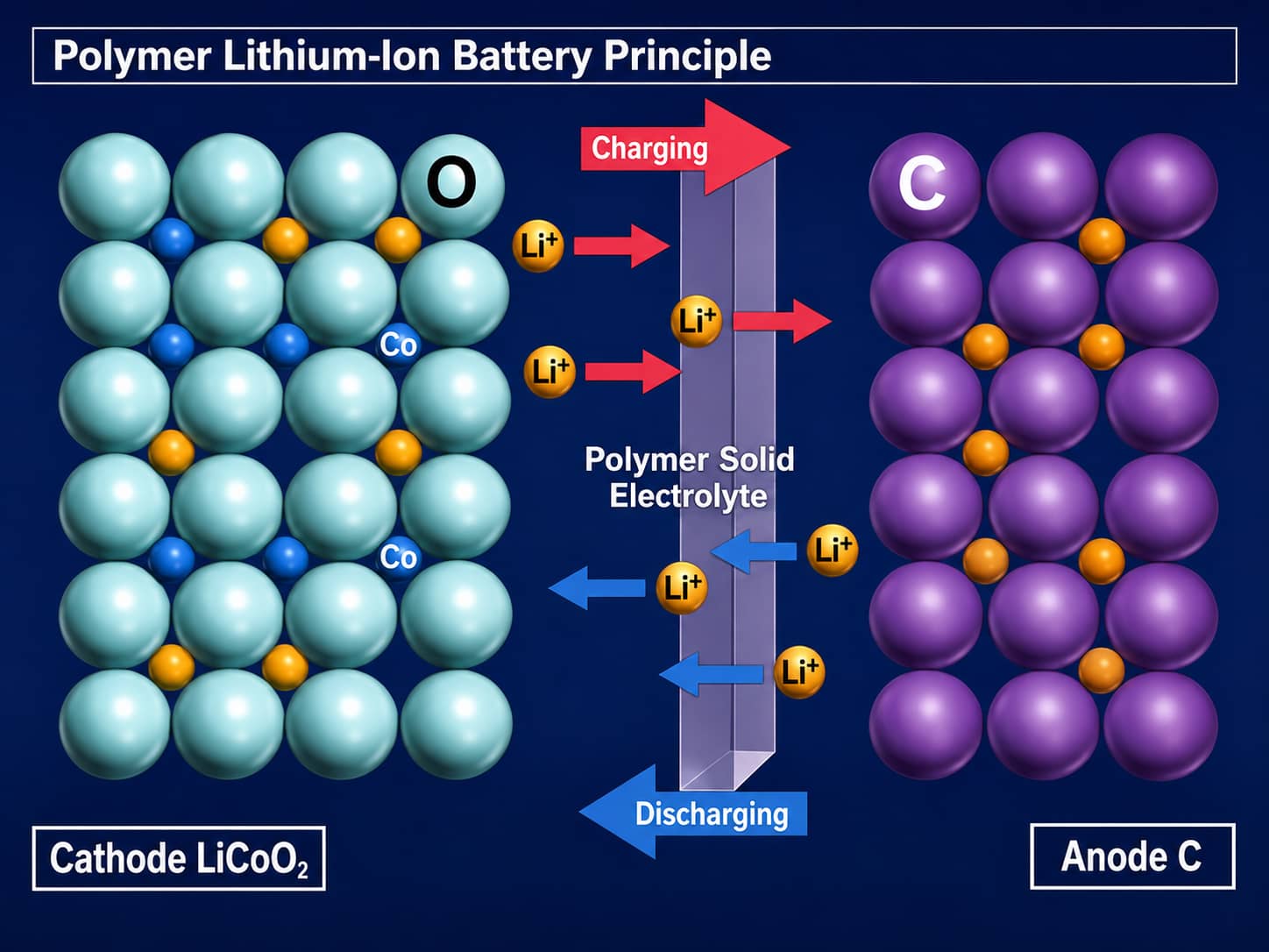
Battery separators prevent direct contact between the cathode and anode while allowing lithium ions to move through the cell. This guide compares PP, PE, trilayer, ceramic-coated, adhesive-coated, cellulose, and PET separators, and explains how to select, test, and troubleshoot them for different battery applications.
1. Core Function of Lithium-Ion Separators
Fast Preliminary Separator Selection Matrix
| Core Project Requirement | Separators For Preliminary Evaluation | Key Indicators To Verify |
|---|---|---|
| Low-cost consumer cells, strict cost control | Single-layer dry PP base film | Thickness, Gurley value, thermal shrinkage, puncture strength |
| Thin high-energy density passenger EV cells | Wet-process PE base film | Pore uniformity, tensile strength, coating compatibility |
| Power batteries with high thermal safety demand | Ceramic coated PP/PE / trilayer membrane | Coating adhesion, high-temp dimensional stability, electrolyte wettability |
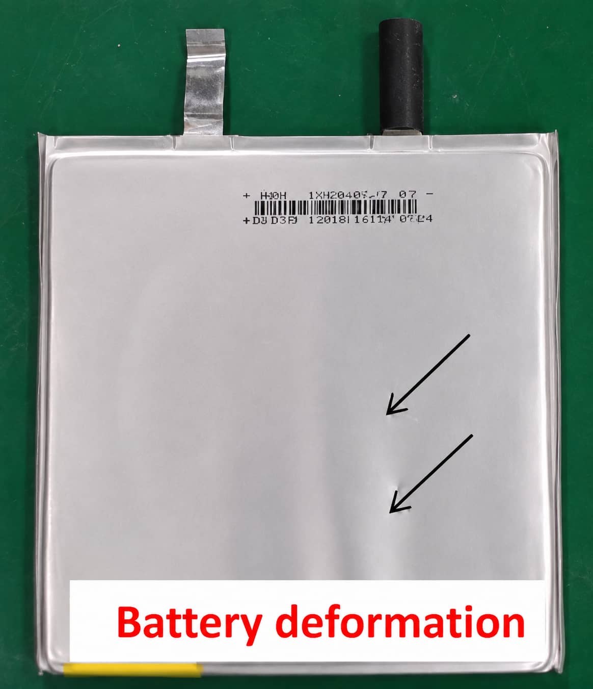
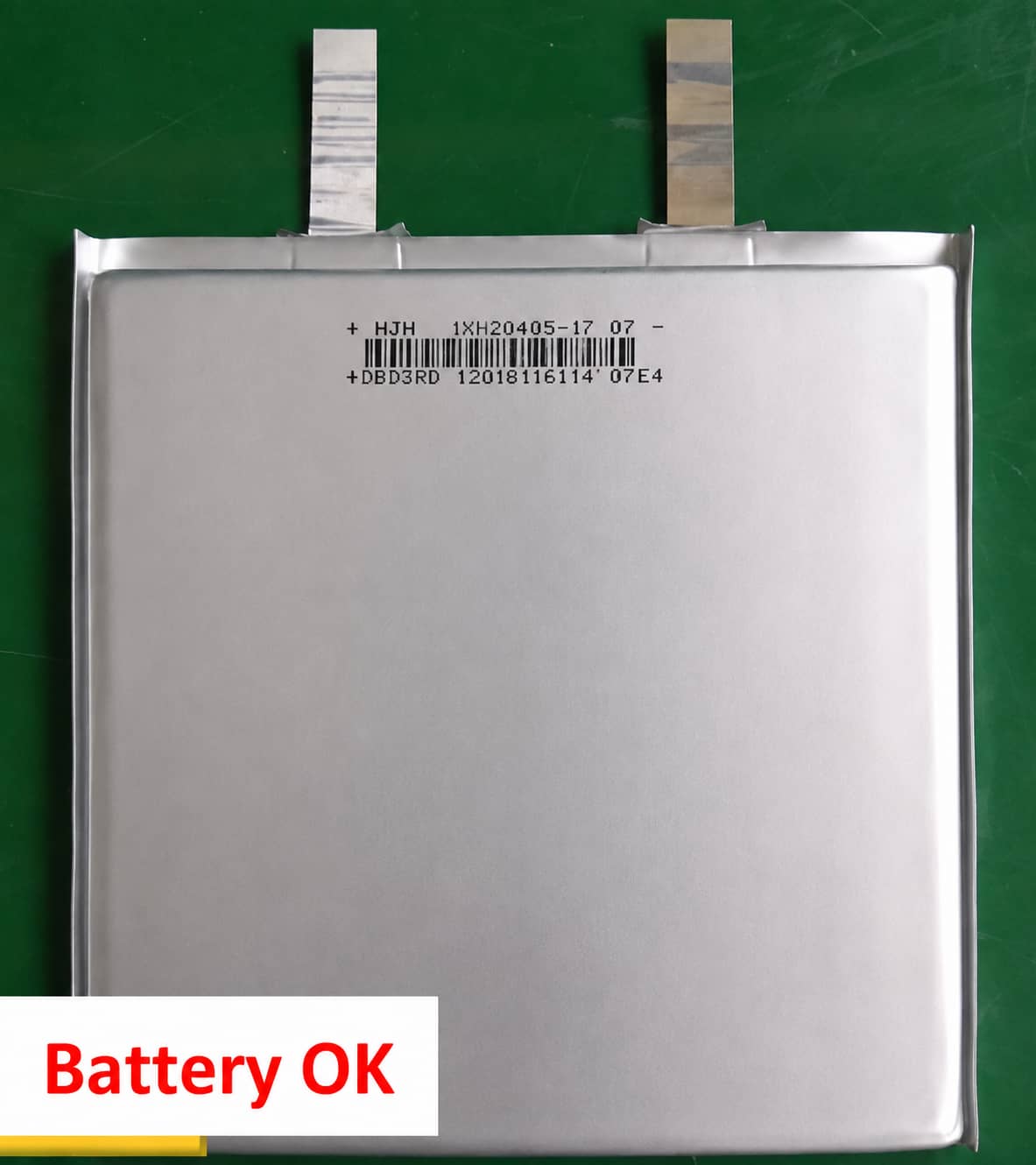
| High-energy cells with silicon-carbon anodes prone to expansion | Double-sided adhesive coated separator | Hot-press bonding strength, post-cycle cell deformation |
| High-temperature industrial energy storage systems | PET ceramic composite separator | Melting point, long-term electrolyte compatibility |
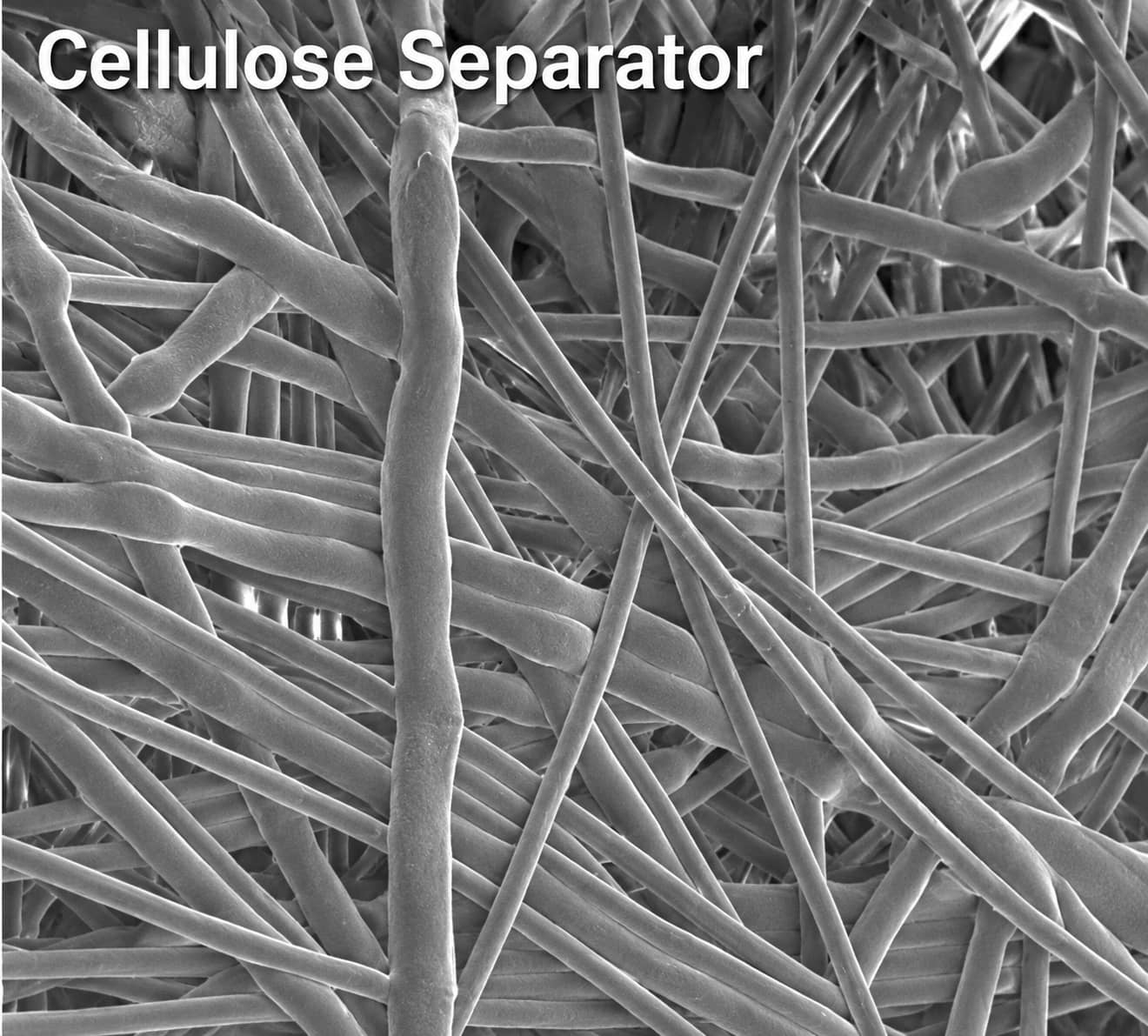
| Ultra-fast charging high-power devices | Straight-pore cellulose separator | Porosity, ion transport tortuosity, rate capacity retention |
2. Mandatory Performance Metrics & Training Reference Ranges
- Complete electronic insulation to physically separate positive and negative electrodes
- Appropriate pore size & porosity to reduce ion transmission resistance
- Excellent chemical & electrochemical inertness against electrolyte corrosion
- Superior electrolyte wettability and liquid retention capacity
- Balanced mechanical properties (puncture & tensile strength) with ultra-thin design options
- Stable flatness and dimensional consistency under assembly pressure
- Reliable thermal shutdown passive safety mechanism
- Higher comprehensive performance standards required for power battery composite separators
Detailed Test Test Parameters
- Pore Size & Pore Distribution
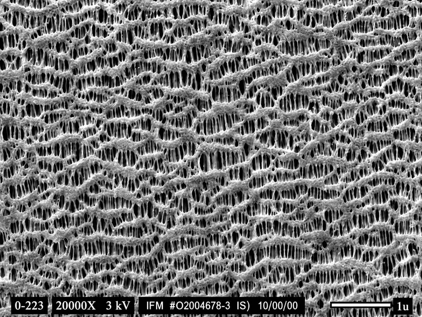
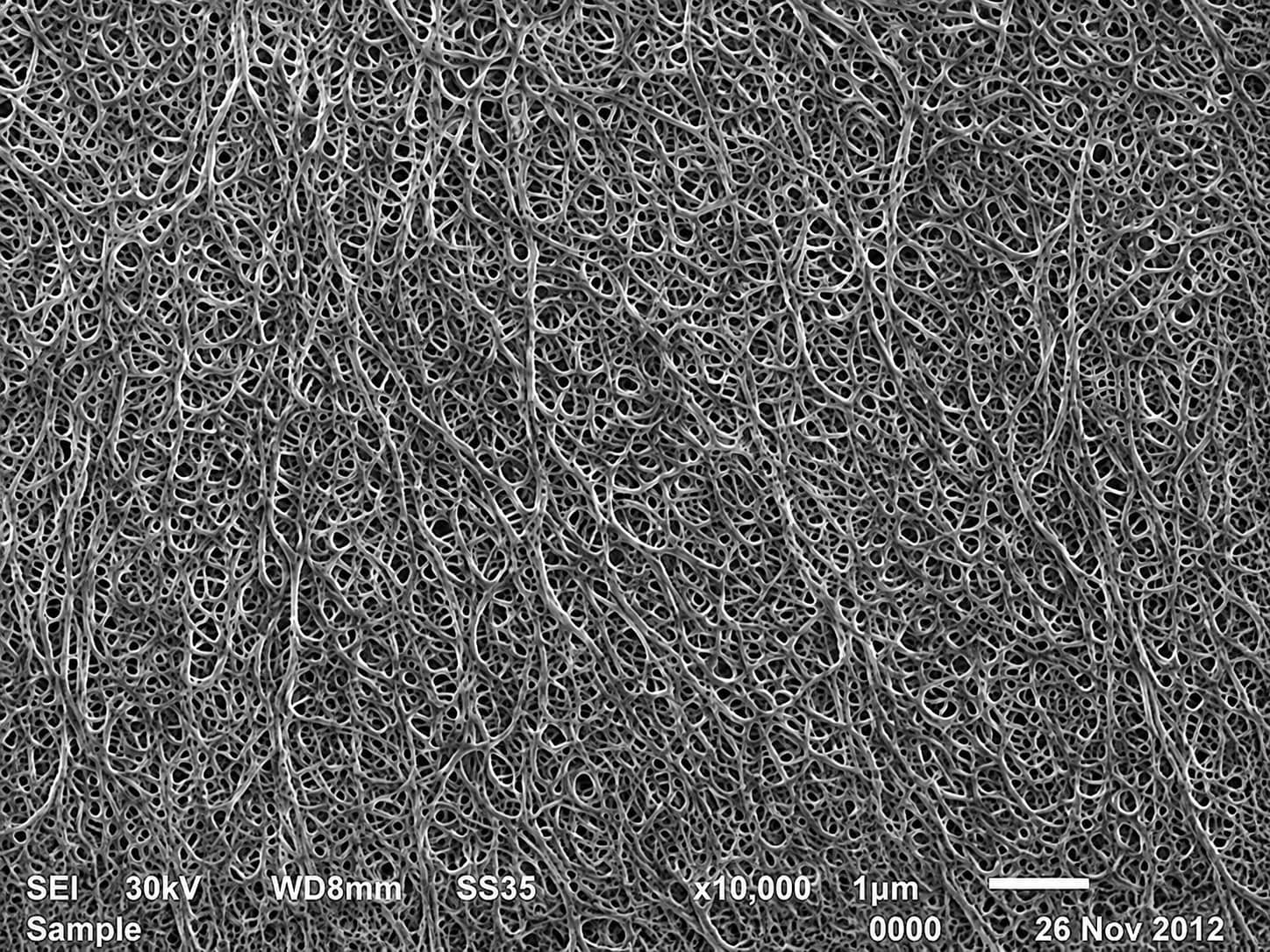
Pore dimension is determined by film manufacturing technology. Uneven pore distribution causes inconsistent current density inside cells, triggering lithium dendrite growth that may pierce separators. Training reference pore range: dry film 0.01~0.3μm; wet film 0.01~0.1μm.
- Porosity
Defined as the volume ratio of internal micropores to total separator volume. Training reference range: 35%~60%. Higher porosity improves ion conductivity but lowers mechanical puncture resistance.
- Gurley Air Permeability Index
A higher Gurley value generally implies slower gas penetration and higher ionic transport resistance, but overall cell internal resistance is also affected by separator thickness, electrolyte uptake and electrode interfaces, and cannot be judged solely by Gurley data.
- Thermal Dimensional Stability
Refers to the shrinkage rate of separators after constant high-temperature baking, the core safety indicator to evaluate thermal runaway risks.
- Automatic Thermal Shutdown Mechanism
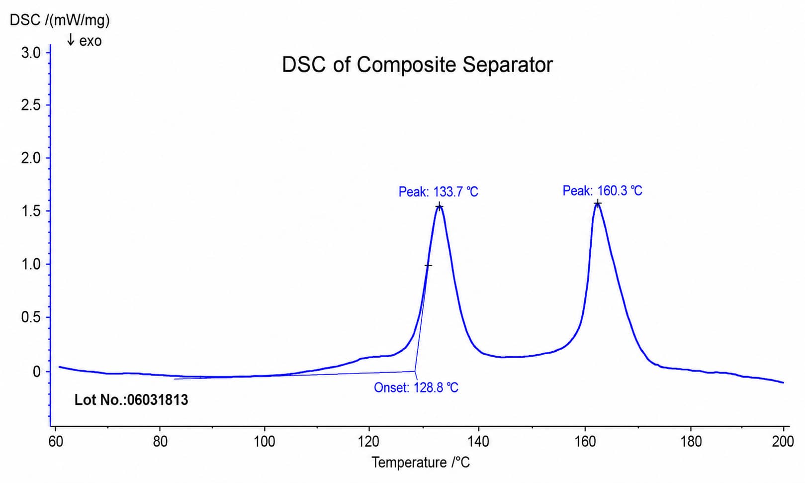
Passive safety protection unique to polyolefin separators. When temperature reaches polymer melting point, internal micropores close to block lithium ion migration and cut off electrochemical reactions. PP reference shutdown onset: ~145°C; PE reference shutdown onset: ~130°C.
- Mechanical Strength
Includes puncture resistance, uniaxial and biaxial tensile performance. Biaxially stretched separators maintain consistent tensile strength in horizontal & vertical directions.
3. Full Classification of Commercial Separator Materials
4. Dry vs Wet Polyolefin Base Separator Comparison
4.1 Dry Process PP Separator Manufacturing Principle
4.2 Wet Process PE Separator Manufacturing Principle
Dry & Wet Process Comparative Table
| Comparison Dimension | Dry Process Separator (PP Mainstream) | Wet Process Separator (PE Mainstream) |
|---|---|---|
| Production Flow Complexity | Relatively simple | Complex thermally induced phase separation |
| Fixed Asset Investment | Lower equipment cost | High manufacturing line investment |
| Process Control Difficulty | Medium precision requirement | High precision for solvent extraction |
| Applicable Raw Material | PP primary; PE rarely used | PE primary; PP optional but uncommon |
| Production Cost | Lower overall manufacturing cost | Higher raw material & processing cost |
| Typical Application Scenarios | Cost-controlled low-medium performance batteries | Thin high-energy-density premium EV cells |
| Polymer Melting Point | PP: 160°C | PE: 140℃ |
| Reference Shutdown Temp | ~145℃ | ~130℃ |
| Thermal Shrinkage Feature | Lower training-reference shrinkage range | Larger training-reference shrinkage range |
| Reference Pore Size Range | 0.01~0.3μm directional pores | 0.01~0.1μm |
| Production Environmental Impact | Solvent-free, eco-friendly production | Solvent used with full recycling system required |
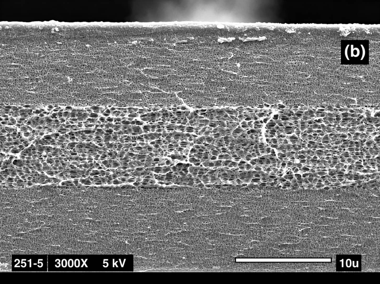
5. Trilayer PP/PE/PP Composite Separator Introduction
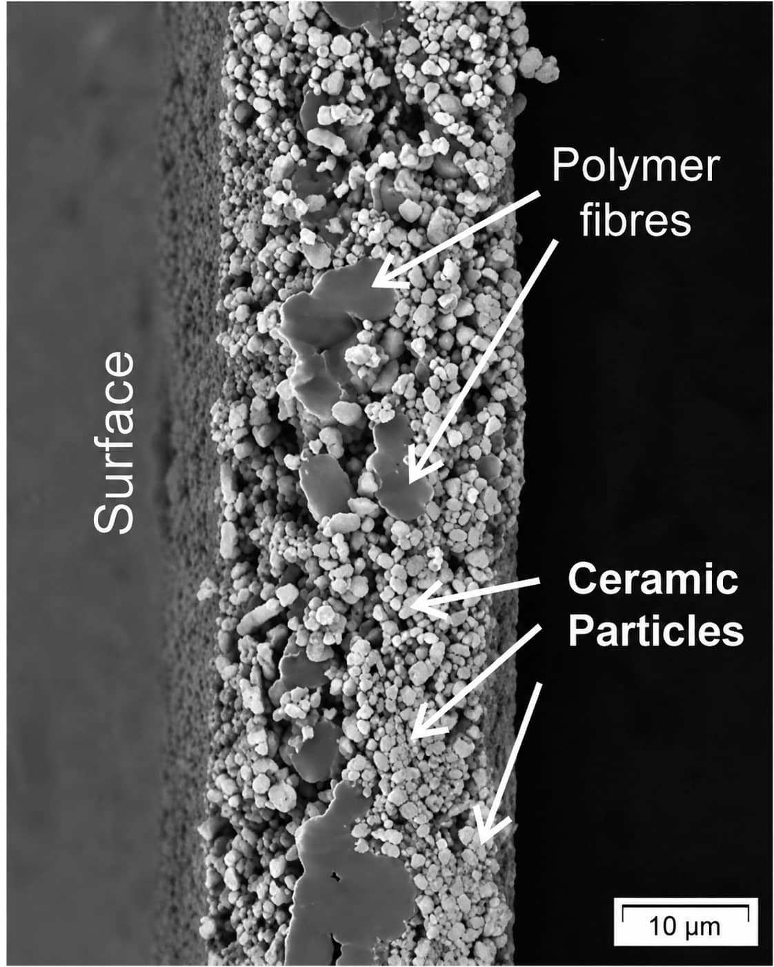
6.1 Ceramic Inorganic Coated Separator
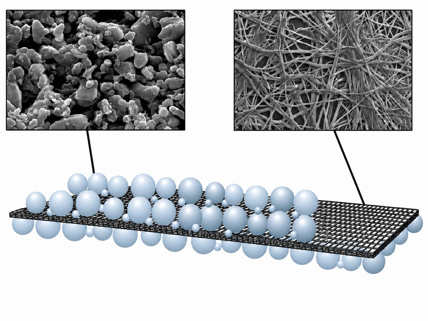
- Restrains high-temperature thermal shrinkage of PP/PE base film, reducing thermal runaway risks such as cell combustion and explosion. Ceramic coatings can improve puncture resistance, though puncture failure must also rule out electrode burrs, foreign particles and lithium dendrite factors.
- Optimizes electrolyte wettability and liquid retention capacity. Improved interface performance may extend cycle life under matched electrode & electrolyte systems, but coating quality directly determines actual improvement effect.
6.2 Adhesive Coated Separator
7. New-Generation High-Rate & High-Temp Special Separators
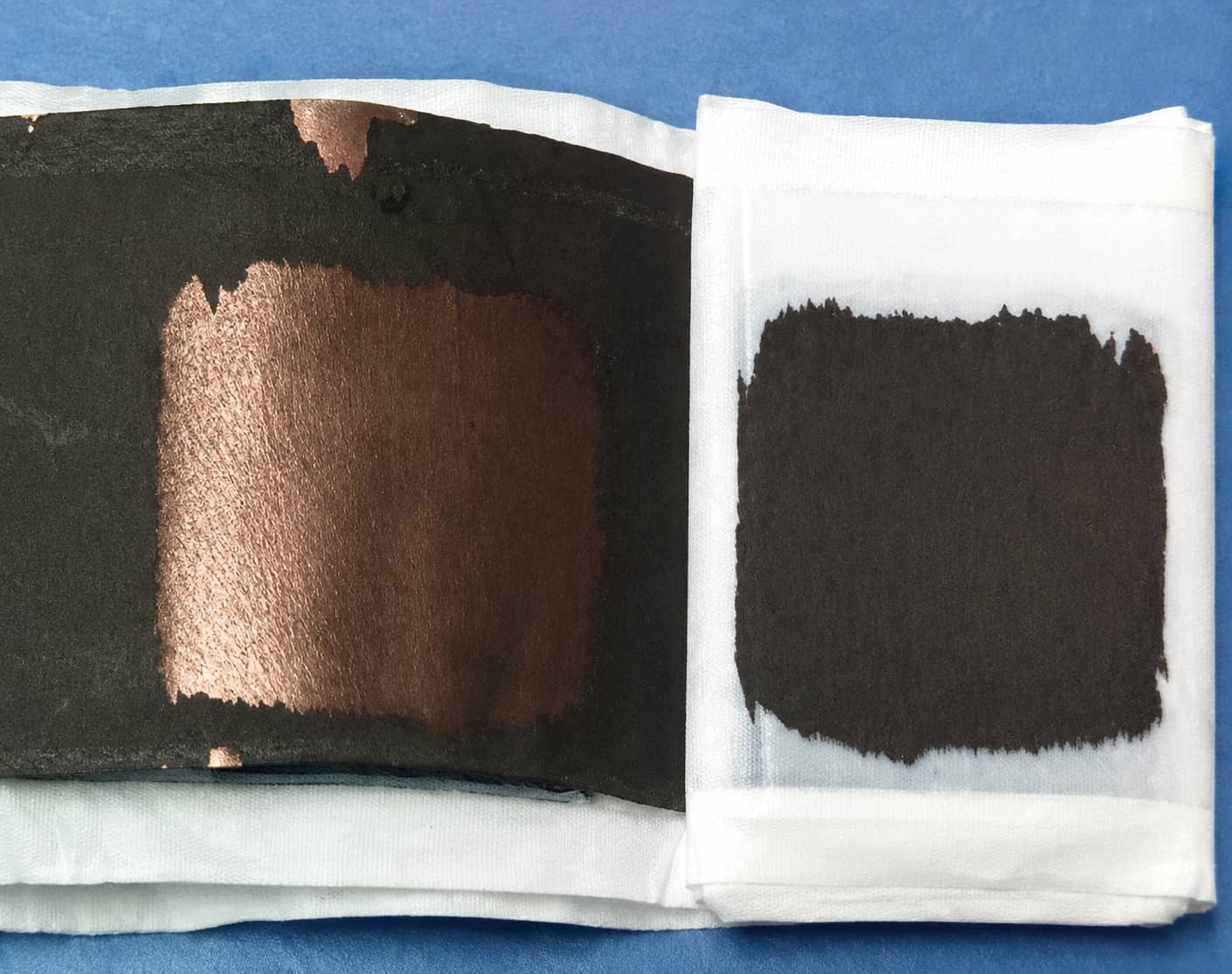
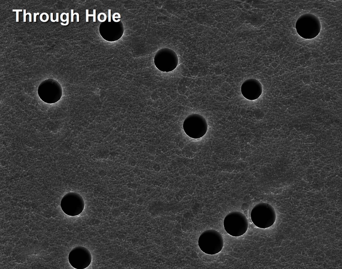
7.1 Cellulose Straight-Pore Separator
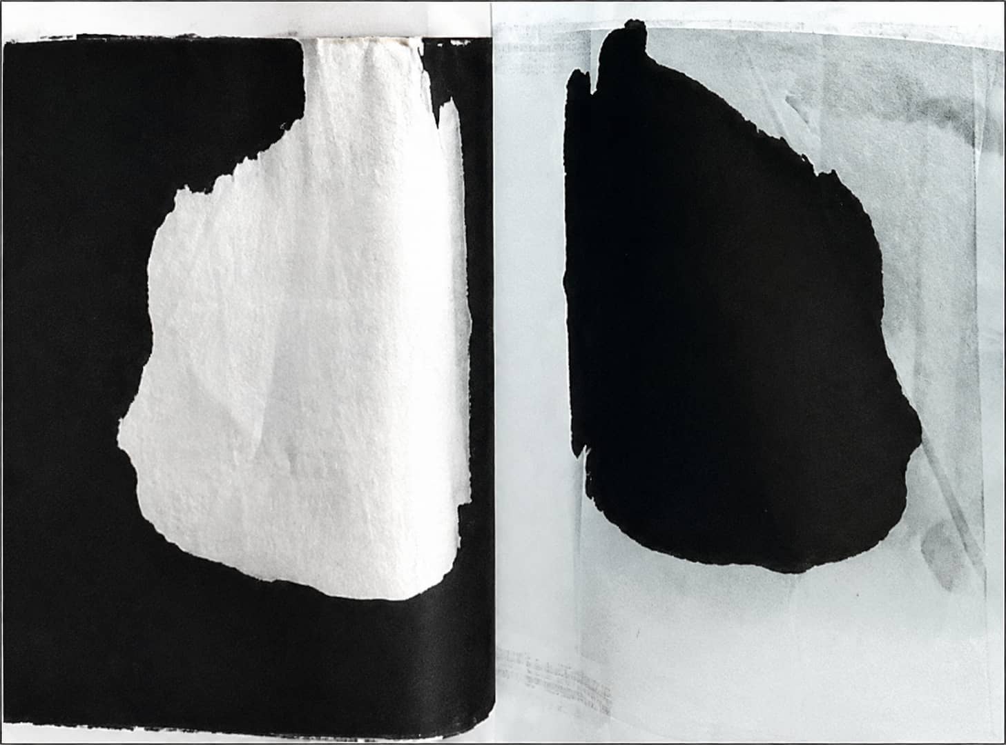
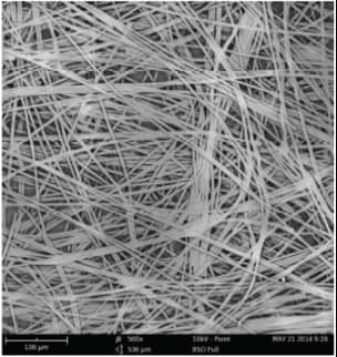
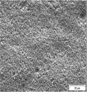
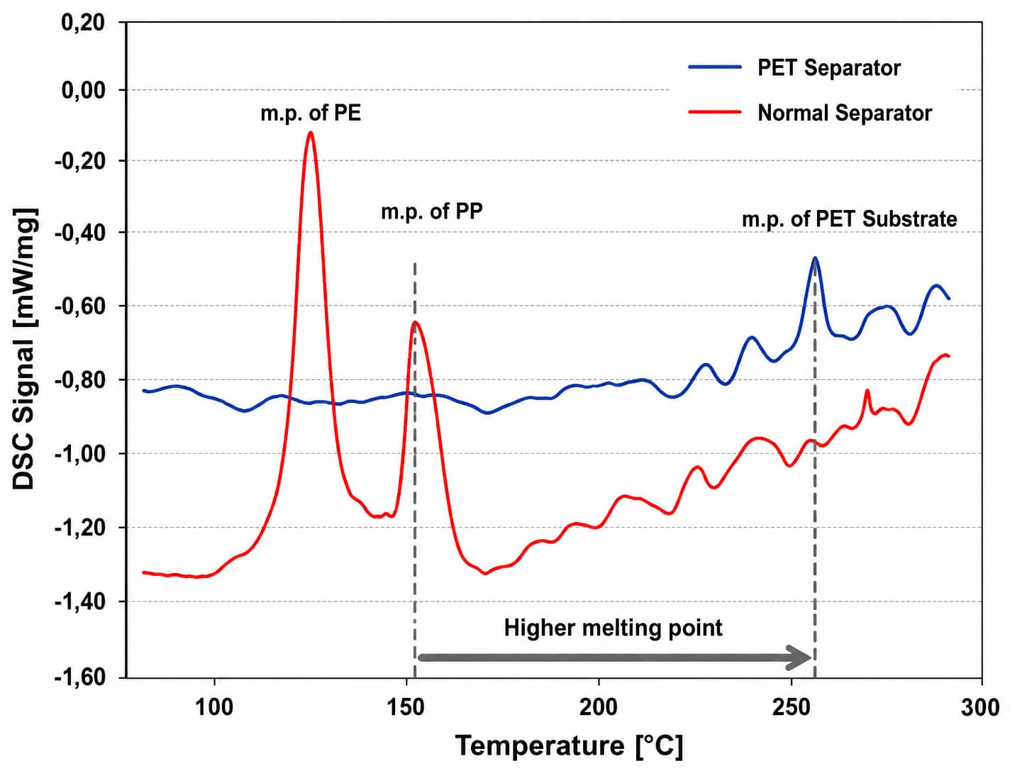
7.2 PET Ceramic Composite Separator
8. How To Diagnose Cell Defects Linked To Separators (Evidence-Based Table)
| Observed Cell Abnormality | Priority Test Evidence To Collect | Separator-Related Hypothesis | Other Root Causes To Exclude First |
|---|---|---|---|
| Batch inconsistent internal resistance | Separator full-width Gurley test, coating thickness uniformity | Uneven pore distribution / unstable coating thickness | Electrode coating inconsistency, welding resistance, incomplete electrolyte infiltration |
| Internal short circuit after high-temperature cycling | Post-mortem separator inspection, thermal shrinkage test | Uncoated polyolefin severe shrinkage, uneven pores induce lithium dendrite puncture | Electrode burrs, foreign metal particles, uneven electrode stacking |
| Pouch cell bulging & wrinkling after long cycles | Hot-press adhesion test of separator & electrodes | Ordinary uncoated separator lacks bonding function | Excess water inside cell, insufficient formation degassing, electrolyte side reactions |
| Poor high-rate discharge capacity retention | Separator porosity & Gurley value measurement | Low porosity / high tortuosity blocks lithium ion transmission | Electrode active material ion diffusion limitation, high electrolyte viscosity |
| Ceramic coating shedding during winding | Separator peel strength test, coating surface micrograph | Insufficient binder dosage in coating slurry | Excessive winding tension, separator surface friction damage |
| Rapid capacity fading with long cycles | Separator electrolyte wettability & liquid retention test | Poor ceramic coating liquid absorption | Electrode material pulverization, electrolyte consumption over cycles |
9. Complete Separator Validation Workflow (Raw Film → Full Prototype Cell)
- Raw Base Film Inspection: Thickness, porosity, Gurley value, pore size distribution, puncture/tensile strength, thermal shrinkage, DSC shutdown temperature
- Coated Separator Semi-Finished Test: Coating weight per unit area, coating peel strength, surface pinhole visual inspection, electrolyte absorption & retention rate
- Electrolyte Compatibility Test: Long-term soaking stability, dimensional change after liquid absorption
- Small Coin Cell Screening: Rate discharge performance, 100-cycle capacity retention, high-temperature storage short-circuit risk
- Pouch Full Cell Formal Verification: Long-cycle thickness change, high-rate charging stability, thermal abuse safety performance
- Mass Production Simulation Test: Winding tension tolerance, coating abrasion resistance during assembly
10. Industry Development Trends of Separator Materials
- Near-term industrial optimization direction: Cost reduction for standard polyolefin base films; double-sided ceramic coated separators as mainstream upgrade for power batteries
- Medium-term functional evolution trend: Multi-functional composite separators integrating ceramic heat-resistant layer adhesive bonding layer to simultaneously solve thermal safety and electrode expansion deformation issues
- Long-term new material R&D Focus: High-melting-point PET/PI non-woven composite separators, high-throughput straight-pore cellulose separators for ultra-fast charging applications
- Ultimate technical evolution route: Solid/gel electrolyte systems integrate separator & electrolyte functions, gradually replacing traditional microporous separators for solid-state batteries
11. FAQ
Q1: What is the core difference between dry PP separator and wet PE separator?
Q2: Are ceramic coated separators mandatory for all power batteries?
Q3: How can adhesive coated separators improve silicon-carbon blended pouch cells?
Q4: What application scenarios suit cellulose separators?
Q5: What safety advantages do PET ceramic separators have over ordinary PP/PE separators?
Q6: How to judge whether a separator’s Gurley value meets requirements?
12. Conclusion
Related Products & Services
Use Canrd products and R&D services to turn battery knowledge into practical experiments.
Coin Cell Case
ProductCoin cell cases for validating materials and electrochemical concepts from the article.
Use coin cell cases in your next test →Sodium Electrolyte
CategoryElectrolytes for sodium-ion battery research, compatibility tests, and cell validation.
Shop sodium electrolyte for validation →Cell Fabrication
ServiceGet support building dry cells, assembled cells, or custom formats for R&D validation.
Request cell fabrication support →Experimental Materials
CategoryBrowse materials for follow-up experiments, benchmarking, and product development.
Browse experimental battery materials →