

 contact@canrd.com

 +86 18928276992


Details
Delivery lead time: 3–5 working days. For bulk orders or customized products, please contact us to confirm the exact lead time.
Caution:
- The alloy sheets are moisture-sensitive. Keep them tightly sealed before use, and avoid contact with or storage in environments containing moisture or solvent vapors.
- The normal color of the alloy sheets is silver-gray or dark silver-gray. Apparent color differences may occur due to variations in lighting and viewing angle and are considered normal. If the sheets appear dark yellow or bluish-purple, they may have deteriorated due to moisture exposure. Please inspect the condition of the alloy sheets upon receipt and store them strictly in accordance with the specified requirements to prevent degradation.
3. Product Advantages
✓ Precisely Controlled Composition: The Li:In atomic ratio is strictly controlled within the specified range. The mature manufacturing process and high batch-to-batch consistency ensure the reproducibility of experimental results.
✓ Ready to Use, Saving Time and Effort: Eliminates the need for researchers to separately cut, stack, align, and assemble lithium foil and indium foil, as well as the high cost of purchasing the two foils separately. The product offers consistent and controllable quality, saves valuable research time, and accelerates R&D progress. The integrated alloy sheet prevents delamination; its gradient alloy structure promotes rapid and uniform lithium deposition and can effectively shorten the rest period before battery testing. Individually compartmentalized tablet-style packaging allows convenient, on-demand use.
✓ Reduced Interfacial Impedance: The lithium–indium alloy is optimized for compatibility with sulfide solid-state electrolytes such as LGPS and LPSCl, enabling the formation of a stable, low-impedance interface and effectively reducing cell polarization.
Chemical Stability: Pure lithium is a highly powerful reducing agent and undergoes thermodynamically spontaneous and continuous interfacial side reactions with most sulfide electrolytes, such as Li₁₀GeP₂S₁₂. These reactions generate unstable, highly resistive interphases containing species such as Li₂S and Li₃P.
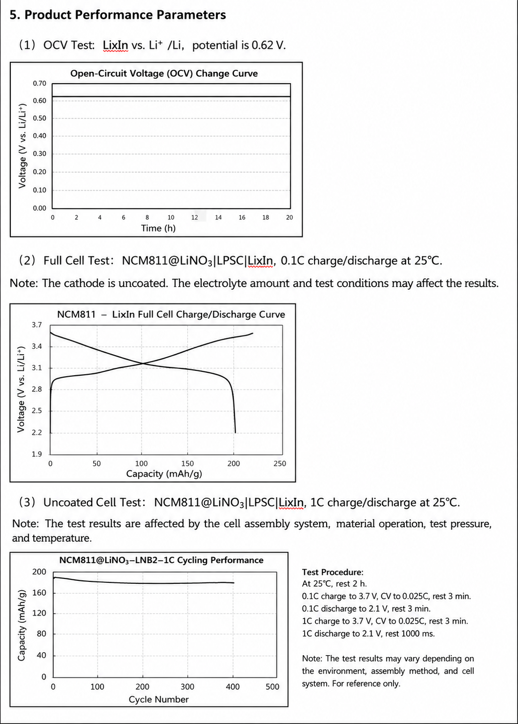
Potential Advantage: Lithium–indium alloys, such as LiIn, have an operating potential of approximately 0.62 V vs. Li⁺/Li, which is higher than the 0 V potential of pure lithium. This places the alloy within the thermodynamic stability window of many sulfide electrolytes, stated here as approximately 1.5–2.5 V, thereby significantly suppressing interfacial side reactions.
✓ Improved Cycling Stability: In sulfide-based all-solid-state batteries, pure lithium anodes undergo substantial volume changes during cycling, theoretically exhibiting unlimited expansion, accompanied by severe lithium dendrite growth and the formation of “dead lithium.” These effects repeatedly disrupt the solid–solid contact interface with brittle sulfide electrolytes such as LGPS and LPSC, resulting in continuously increasing interfacial impedance and rapid capacity degradation. Compared with pure lithium anodes, lithium–indium alloy anodes can suppress lithium dendrite growth, thereby improving the safety and cycle life of all-solid-state batteries
4. Detailed Product Specifications
| Item | Specification |
|---|---|
| Atomic Ratio (Li:In) | 0.5–1.0 (The exact ratio is proprietary.) For specific requirements, please contact customer service for customization. Minimum order quantity: 50 pieces. |
| Appearance | Composite-structure metallic sheets with a silver-white or silver-gray appearance and a smooth, flat surface. The apparent color may vary under different lighting conditions and viewing angles. |
| Standard Dimensions | Ø10 mm, approximately 400 μm thick. Other dimensions can be customized upon request, including discs and square sheets. Diameter or side length: 6–20 mm; thickness: >300 μm. Pricing depends on the dimensions and manufacturing complexity. Tooling charges may apply. |
| Theoretical Capacity (Approx.) | >15 mAh (An appropriate CB value must be determined by the user. The degree of delithiation varies depending on the cell chemistry and current density.) |
| Operating Potential (vs. Li⁺/Li) | ~0.62 V |
| Applications | All-solid-state lithium-metal batteries; mechanistic studies of the solid electrolyte interphase (SEI); performance evaluation of novel solid electrolyte materials. |
| Packaging | Individually compartmentalized tablet-style packaging under an argon atmosphere, sealed in an aluminum-plastic laminated pouch. Avoid vigorous shaking and impact. |
| Shelf Life | Two months when stored in unopened vacuum-sealed packaging. Use as soon as possible after opening. Store under vacuum or an argon atmosphere, and avoid contact with water, oxygen, organic solvents, or similar substances. |
6. Receipt and Inspection
Inspection upon Receipt: After receiving the package, first inspect the outer packaging for any visible damage. The inner sealed pouch or aluminum-laminated pouch must remain intact, with no signs of leakage.
Immediate Transfer: The product is packaged in two layers of aluminum-laminated pouches, with the inner package filled with argon. After removing only the outermost pouch, place the remaining sealed package in the glovebox antechamber for transfer; complete unpacking is not required at this stage. Transfer the unopened inner package into the glovebox as soon as possible. Prolonged storage in air is not recommended, even when the package remains sealed.
7. Handling Instructions Inside the Glovebox
Environmental Requirements: All operations must be performed in a high-purity inert-atmosphere glovebox with both moisture and oxygen levels below 0.1 ppm.
Opening and Handling:
- Open the outer aluminum-laminated pouch outside the glovebox, promptly transfer the inner package into the glovebox, and carefully open the inner pouch before use.
- Handle the alloy sheets using clean, flat-tip ceramic tweezers or plastic tweezers. Avoid gripping them forcefully with metal tweezers, as this may scratch the surface or introduce metallic contamination.
- It is recommended to store the product in a sealed glass container inside the glovebox. Reseal the container with paraffin sealing film after each use to prevent prolonged exposure to fluctuations in the glovebox atmosphere.
Caution: Avoid vigorous shaking, impact, or dropping of the lithium–indium alloy sheets, as this may cause them to fracture.
8. Cell Assembly Guidelines
For an all-solid-state cell such as NCM811 | LPSC | LixIn, the typical assembly sequence is:
Solid electrolyte layer → Cathode layer → Alloy anode layer
Both material selection and stack pressure can significantly affect cell testing results. Therefore, a constant and appropriate pressure must be applied. The recommended assembly pressure and testing pressure for the alloy layer are 200 MPa. A constant-pressure cell fixture is recommended to maintain stable pressure throughout cycling.
This product is a ready-to-use alloy anode and requires no additional pretreatment. The alloy sheet can be used directly for cell assembly. After assembly, it is recommended to allow the cell to rest for 10 hours so that the applied pressure and the internal cell system can stabilize.
The resting time may be shortened after users have conducted their own validation. Since the product has already undergone alloying treatment, an appropriately reduced resting period may help improve experimental efficiency.
9. Recommended Electrochemical Testing Parameters
(1) Voltage Window
◆ Half-Cell Testing:
When lithium metal is used as the counter electrode, the recommended voltage window is 0.5–1.0 V vs. Li⁺/Li. This voltage range helps maintain stable cycling near the LiIn phase while preventing excessive lithiation or delithiation.
◆ Full-Cell Testing:
When paired with cathode materials such as NCM811, the recommended full-cell operating voltage window is approximately 2.1–3.7 V, depending on the cathode material and the electrochemical stability of the electrolyte. The operating potential plateau of this product is approximately 0.62 V vs. Li⁺/Li.
(2) Current Density
◆ Initial Activation:
During the first 2–3 cycles, it is recommended to charge and discharge the cell at a low current of 0.1C or 0.1 mA/cm² to establish a stable electrode–electrolyte interface.
◆ Long-Term Cycling:
After activation, the current rate may be gradually increased to 0.2C–1C for long-term cycling tests. Cycling performance may decrease as the current density increases.
(3) Expected Performance
◆ Initial Coulombic Efficiency: In half-cell testing, the initial Coulombic efficiency is generally high due to the intrinsic reversibility of the alloy. In full-cell testing, the overall initial Coulombic efficiency is mainly limited by that of the cathode material, such as NCM811.
◆ Cycle Life: Under optimized conditions, stable cycling for several hundred to more than one thousand cycles may be achievable.
10. Safety and Disposal
◆ Safety Warning: Although this product is more stable than pure lithium, it remains a reactive material. Exposure to air or water is strictly prohibited, as it may generate heat and release hydrogen gas, creating a risk of fire.
◆ Disposal: When disposal is required, place the product in a fume hood and ensure that the surrounding area is clear of combustible materials. Allow it to undergo controlled oxidation under ventilation, or immerse it in anhydrous ethanol or mineral oil so that the reaction proceeds slowly and completely. Dispose of the remaining material as chemical waste in accordance with applicable regulations.
11. Additional Information
Based on currently available academic research, this lithium–indium alloy sheet is designed to utilize the lithiophilic properties of indium. In theory, it may promote uniform lithium deposition, suppress lithium dendrite growth, and improve interfacial contact with certain solid-state electrolytes. Actual performance may vary depending on the specific battery chemistry, process parameters, and operating conditions.
When used as an anode material, its effectiveness in suppressing dendrite growth and reducing interfacial impedance is highly dependent on the electrolyte type, interfacial pressure, current density, cathode matching, and overall cell assembly process. Users are advised to conduct comprehensive testing to optimize the relevant parameters.
The product specifications and performance information provided by the company are based on currently available academic literature and representative testing conditions and are intended solely for reference and research purposes. Due to the complexity of battery systems and the uncontrollable nature of individual application conditions, the company makes no warranty or commitment regarding the product’s final performance in actual cells and accepts no liability for any resulting direct or indirect losses. Users are responsible for conducting a comprehensive evaluation and testing of the safety of the cells they manufacture.
R&D 지원이 필요하신가요?
주요 제품 카테고리를 확인하고 배터리 소재를 Canrd R&D 서비스와 연결하세요.
실험 소재
카테고리배터리 연구용 양극, 음극, 전해액, 분리막 및 기타 소재.
양극, 음극 및 전해액 소재 보기 →실험 장비
카테고리파일럿 라인, 지그 및 테스트 워크플로용 배터리 실험 장비.
배터리 실험 장비 보기 →전극 및 셀
카테고리R&D 검증을 위한 맞춤 전극, 드라이 셀 및 배터리 셀 부품.
맞춤 배터리 전극 및 셀 보기 →나트륨 전해액
카테고리나트륨 배터리 연구 및 검증을 위한 나트륨 이온 전해액 옵션.
나트륨 배터리 전해액 보기 →R&D 서비스
서비스소재 평가부터 셀 제작 및 고장 분석까지 전주기 배터리 R&D 서비스.
Canrd R&D 서비스 살펴보기 →소재 평가
서비스배터리 소재의 특성 분석, 전기화학 테스트 및 호환성 평가.
배터리 소재 평가하기 →전극 제작
서비스목표 화학계와 공정 요구에 맞춘 맞춤 전극 시트 및 롤.
전극 제작 요청하기 →셀 제작
서비스R&D 검증을 위한 드라이 셀, 조립 셀 및 맞춤 셀 형식.
맞춤 연구 셀 제작하기 →문의
페이지Canrd가 프로젝트에 맞는 제품, 소재 및 서비스를 연결해 드립니다.
제품 및 R&D 지원 받기 →
