
Winding & Lamination Process for Lithium-ion Pouch Cells
canrd July 22, 2026 69
Introduction
Lithium-ion pouch cell core assembly is divided into two mainstream production routes: winding process and zig-zag lamination (stacking) process, which follow the slitting, ultrasonic welding and electrode taping/gluing procedures, and precede aluminum-plastic film forming, baking, electrolyte injection formation workflow in full battery manufacturing. The core quality of bare cell directly determines battery safety, internal resistance, capacity consistency and cycle life, making winding and lamination the most critical cell forming processes after electrode sheet preparation. This guide systematically explains equipment, operation standards, key control points, common defects, quality inspection standards, process logic differences between winding and stacking, as well as aluminum-plastic shell pre-forming matching requirements, fully combining mass production workshop actual standards for soft pack lithium batteries.
Why Are Winding & Stacking The Most Critical Cell Assembly Step?
Most battery engineers and factory QA teams regard bare cell forming as the decisive stage that determines finished cell performance, consistency and long-term safety. There are four core root reasons behind this industry consensus:
- Direct control over internal short-circuit risk
All slitting burrs, exposed metal foil and misaligned insulating tape converge here. If winding/stack alignment fails, hard metal fragments will pierce the separator during charge-discharge expansion, triggering micro-shorts, swelling or thermal runaway. Upstream defects from slitting cannot be fully eliminated—only standardized winding/stack rules block these hazards.
- Determines cell capacity & consistency
Anode-cathode overlapping tolerance directly impacts usable lithium ion storage space. Uneven winding tension or stacking offset creates inconsistent active material utilization across batches, leading to wide capacity grading gaps after formation.
- Decides rate discharge performance
Current transmission path length differs drastically between wound and laminated cores. Misaligned tabs, loose winding or uneven stacking lengthen ion migration distance, raising internal resistance and limiting fast-charging capability.
- Shapes long cycle lifespan
Poor forming creates localized lithium plating areas. Separator wrinkles, layer gaps or edge misalignment cause uneven SEI film growth during cycling, accelerating capacity attenuation and shortening service life.
Every upstream process—electrode coating, calendering, slitting and tab welding—passes quality risks downstream to winding/stacking, making this stage the last critical quality checkpoint before packaging.
How Upstream Slitting Quality Ruins Winding Outcomes (Cross-Process Topic Cluster Link)
The slitting process is the direct precursor to winding/stacking, and slitting defects create irreversible forming failures. This section clarifies the causal chain between front-end pole piece processing and core assembly:
- Excessive slitting burrs
Oversized metal burrs cannot be fully covered by green tape. During winding coiling, burrs scratch or puncture separator film, leading to latent short circuits. Industry standards limit burr length to less than half the separator thickness to avoid this issue.
- Width deviation & edge warping
Uneven slitting edges create continuous offset during automatic feeding. The anode fails to fully cover the cathode edge, violating the 1.0–3.0mm dimensional safety margin rule.
- Edge wrinkling on electrode rolls
Wrinkled pole pieces cause uneven winding tension. Local loose layers form gaps inside the bare cell, resulting in lithium precipitation after liquid injection.
- Misaligned green protective tape
Off-center taping exposes copper/aluminum foil at pole edges. Winding concentrates exposed foil at overlapping positions, greatly boosting short-circuit probability.
1 Pre-Winding / Pre-Stack Electrode Inspection (What We Need Before Forming)
Before loading electrodes into winding or stacking machines, all cathode and anode sheets after welding and taping must undergo 100% visual screening to reject defective raw materials.
Mandatory Rejection Defects
- Electrode cracks, surface indentations and deep scratches
- Active material shedding (decarbonization) with exposed copper/aluminum foil
- Green tape failing to fully cover metal foil edges
- Slitting burrs exceeding specification limits
Non-Negotiable Dimensional Matching Standard (Applies to Both Processes)
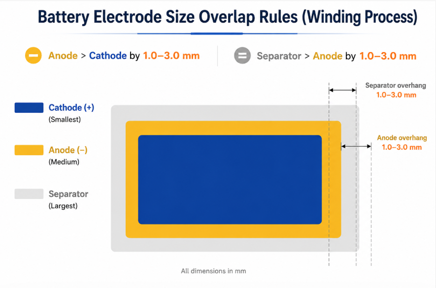
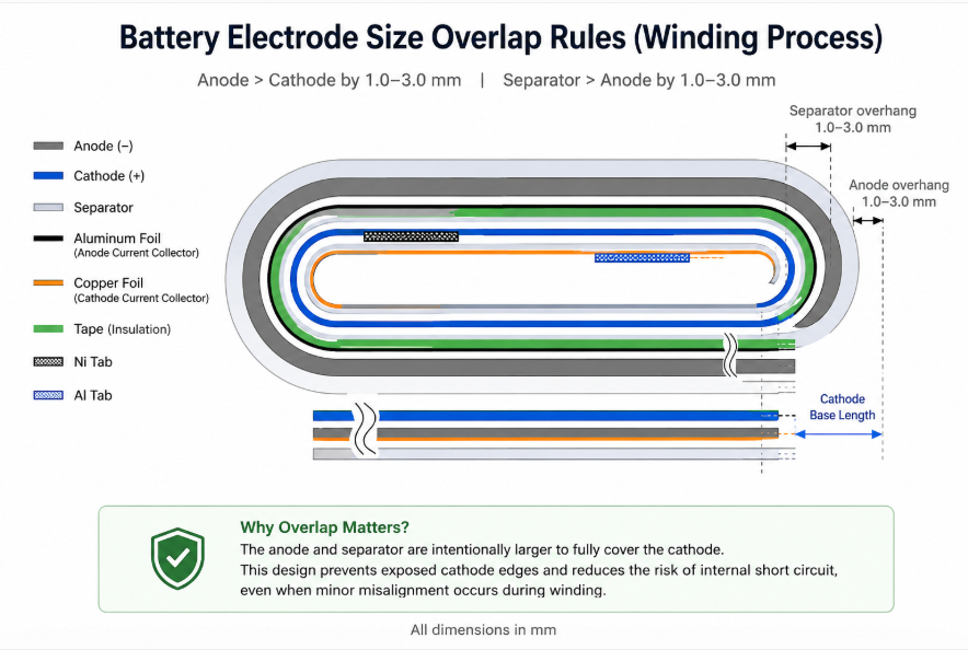
To block short-circuit risks, unified size overlap rules are enforced globally:
- Anode length & width exceed cathode by 1.0–3.0mm
- Separator length & width exceed anode by 1.0–3.0mm This margin guarantees all cathode active material is wrapped by anode copper foil and separator, even with minor feeding offset.
2 Winding Process for Wound Bare Cells
2.1 What Is Winding Technology?
Winding is the traditional continuous bare cell forming process. Long rolled cathode, anode and separator are synchronously fed and spirally coiled into flat rectangular bare cells, mainly used for small-to-medium pouch cells with low-to-medium fast-charging requirements.
2.2 Main Equipment Used in Winding Production Line
Every device undertakes an independent quality control task in the winding workflow:
- Semi-automatic / Fully Automatic Winding Machine: Core coiling equipment, controls feeding speed, tension and tab alignment
- Hot & Cold Press Integrated Machine: Flatten loose wound cores to standard thickness
- Hi-pot Short-Circuit Tester: Real-time double-tab internal resistance detection to screen short-circuited cells
- X-Ray Inspection Machine: Automated measurement of anode-cathode overhang offset

2.3 Standard Winding Operation Flow (How to Perform Winding)
- Thread taped anode, cathode and separator through independent guide rollers
- Calibrate tab center distance and electrode overhang margin per drawing specifications
- Maintain constant tension during synchronous spiral coiling
- Automatically cut separator once target winding layers are reached
- Transfer finished wound bare cell to hot-cold pressing station for shaping
2.4 Winding Defect Troubleshooting Table
| Defect Phenomenon | Root Cause | Targeted Solution | Hidden Risk |
|---|---|---|---|
| Separator wrinkling | Separator tension too low | Adjust feeding roller tension controller | Local lithium plating, capacity fade |
| Anode-cathode offset | Guide roller misalignment, slitting width deviation | Recalibrate feeding track; filter out width-out-of-tolerance electrodes | Edge short circuit |
| Loose winding core | Winding torque insufficient | Increase main coiling motor tension | Cell swelling after liquid injection |
| Tab position deviation | Tab feeding jig shift | Re-fix tab positioning fixture | High internal resistance, poor rate performance |

Why Most Battery Manufacturers Still Prioritize Winding
- Mature, stable equipment supply chain with decades of mass production verification
- Lower upfront production line investment cost vs stacking equipment
- Ultra-high production speed, ideal for large-volume mass manufacturing
- Lower overall defect rate with simple feeding and coiling logic
- Wide compatibility for small power bank, Bluetooth and consumer electronic pouch cells
3 Zig-Zag Lamination (Stacking) Process for Laminated Bare Cells
3.1 What Is Lamination (Stacking)?
Stacking cuts long slit electrode rolls into independent single sheets, then alternates cathode-separator-anode layers via continuous Z-fold separator to form rectangular bare cells. This technology dominates large-capacity power pouch cells and ultra-high fast-charging products.
3.2 Types of Battery Stacking Technology
- Z-fold continuous separator stacking: Single unbroken separator zigzags between electrode sheets, highest alignment precision
- Single-sheet separator stacking: Independent separator cut for each electrode layer, low equipment cost but slower speed
- High-speed automatic stacking: Fully robotic feeding for automotive power cell mass production
3.3 Complete Stacking Production Flow (How to Complete Lamination)
- Slit long electrode rolls into fixed-size single cathode/anode sheets
- Ultrasonic weld aluminum tabs to cathode pieces, nickel tabs to anode pieces
- Apply four-corner green insulating tape to cover sheet edge metal burrs
- Alternately stack electrodes with continuous Z-fold separator isolation
- Fix stacked core edges with adhesive tape to prevent layer dislocation during packaging
3.4 Stacking Core Control Points
- Single electrode cutting dimensional tolerance and burr limits consistent with slitting standards
- Tab welding tension and green tape full coverage requirement
- Layer-by-layer stacking alignment offset control
- Z-fold separator tension to eliminate folding defects
3.5 Stacking Defect Troubleshooting Table
| Defect Phenomenon | Root Cause | Targeted Solution | Hidden Risk |
|---|---|---|---|
| Layer dislocation | Robotic feeding positioning error | Calibrate stacking machine visual alignment system | Uneven capacity distribution |
| Separator tearing | Excessive Z-fold tension | Reduce separator traction force | Direct internal short circuit |
| Corner tape peeling | Insufficient tape pressing pressure | Adjust taping fixture compression | Edge burr piercing separator |
Why Power Cell Brands Like CATL Are Expanding Stacking Lines
- Uniform layer current distribution delivers far lower internal resistance for fast charging
- Higher energy density from tighter electrode stacking with minimal dead space
- Better cycle stability for large automotive pouch cells
- Flexible thickness design for ultra-thick energy storage batteries
4 Winding vs Stacking: Full In-Depth Comparison & Selection Guide
| Comparison Item | Winding Process | Z-Fold Stacking Process | Recommendation Scenario |
|---|---|---|---|
| Mass Production Efficiency | ⭐⭐⭐⭐⭐ Fast continuous coiling | ⭐⭐⭐Discrete single-sheet feeding | Small consumer cells: Winding; Power cells: Stacking |
| Cell Internal Resistance | ⭐⭐⭐ Longer ion path | ⭐⭐⭐⭐⭐ Uniform short current path | Fast-charging products: Stacking |
| Achievable Energy Density | Medium | Higher (less internal gap waste) | High-capacity energy storage: Stacking |
| Equipment & Labor Cost | Low upfront investment | High automation cost | Small-batch low-budget factories: Winding |
| Large Pouch Cell Adaptability | Medium layer alignment error | Excellent uniform stacking | EV power batteries: Stacking |
| Fast Charging Performance | Good | Superior even under high C-rate | 3C fast-charge / EV batteries: Stacking |
| Automation Difficulty | Simple feeding logic | Complex robotic vision alignment | Entry-level factories: Winding |
5 Aluminum-Plastic Film Punch & Forming Matching Process
Why Aluminum-Plastic Laminate Film Is Used for Pouch Cells
Compared with rigid steel or aluminum cylindrical cans, aluminum-plastic composite film delivers irreplaceable advantages:
- Ultra-lightweight structure boosts overall cell energy density
- Flexible forming supports customized ultra-thin, irregular battery shapes
- Superior heat dissipation to reduce thermal runaway risk
- Soft buffer space for gas expansion during formation
- Low packaging cost for consumer electronic mass production
5.1 What Is Aluminum-Plastic Forming?
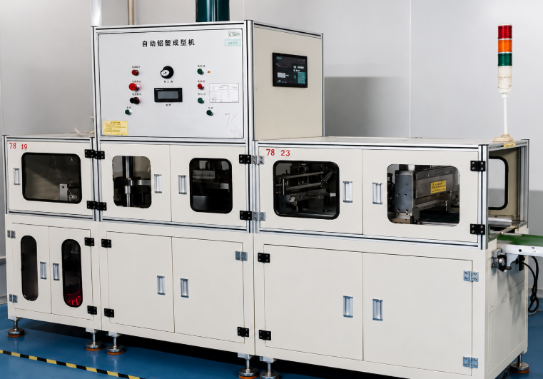
After winding/stacking and X-ray inspection, bare cells enter pre-packaging: the aluminum plastic film punching machine stamps fixed-depth pockets to hold the bare core, followed by top-side heat sealing to temporarily seal the cell cavity.
5.2 Core Forming Equipment
Automatic aluminum-plastic film punching & shell forming machine
5.3 Critical Control Standards & Defect Hazards
- Pocket forming depth tolerance, four-corner R-angle smoothness Sharp R angles crack the aluminum barrier layer, creating pinholes
- Zero pinhole / stretch crack requirement on composite film Pinholes allow ambient moisture to penetrate before baking, reacting with LiPF6 electrolyte to generate corrosive HF, accelerating capacity decay. Cross reference: Vacuum Baking & Electrolyte Injection Guide
6 FAQ
Q1: Why must anode sheets be larger than cathode sheets in winding and stacking?
If the cathode edge extends past the anode boundary, cathode active material directly contacts the separator without copper foil shielding. Slitting metal burrs will puncture the separator during cell expansion, causing permanent internal short circuits.
Q2: What damage does separator folding bring to finished cells?
Folded separators create uneven lithium ion migration paths. Lithium metal precipitates on the anode surface, triggering cell swelling, rapid capacity attenuation and thermal runaway under heavy discharge loads.
Q3: How do aluminum plastic film pinholes affect subsequent baking and liquid injection?
Pinholes break the moisture barrier of the packaging film. Uncontrolled moisture inside the cell decomposes electrolyte to produce HF acid, corroding the SEI protective film and drastically shortening cycle life. Detailed chemical reactions are explained in our baking & injection article.
Q4: What is the core tab difference between winding and stacking?
Winding uses one pair of continuous long tabs per bare cell; stacking welds independent tabs to every single electrode sheet. Multi-tab stacking design greatly reduces internal resistance for high-rate fast-charging batteries.
Conclusion
Winding and Z-fold stacking form the structural backbone of soft-pack lithium-ion cells, bridging front-end electrode processing and post-stage packaging, baking and formation. Understanding why each forming standard exists, comparing process pros and cons, and mastering defect troubleshooting logic allows manufacturers to optimize yield, boost cell consistency and extend cycle life. Select winding for low-cost mass consumer electronics production, and adopt Z-fold stacking for high-energy-density, fast-charging automotive and energy storage pouch cells.
Previous
How to Eliminate Une...Related Products & Services
Use Canrd products and R&D services to turn battery knowledge into practical experiments.
Coin Cell Case
ProductCoin cell cases for validating materials and electrochemical concepts from the article.
Use coin cell cases in your next test →Sodium Electrolyte
CategoryElectrolytes for sodium-ion battery research, compatibility tests, and cell validation.
Shop sodium electrolyte for validation →Cell Fabrication
ServiceGet support building dry cells, assembled cells, or custom formats for R&D validation.
Request cell fabrication support →Experimental Materials
CategoryBrowse materials for follow-up experiments, benchmarking, and product development.
Browse experimental battery materials →