

 contact@canrd.com
 +86 18928276992
Battery Electrode Areal Capacity: How to Calculate and Optimize
Battery electrode areal capacity describes available charge capacity per unit electrode area, with standard unit mAh/cm². It links active-material electrochemical performance, coating mass loading, electrode geometry and full cell design.
Boosting areal capacity can reduce the electrode area required to hit a fixed cell capacity, potentially lowering the proportion of inactive components such as current collectors and separators. However, the net benefit must be confirmed via full-cell calculations under target performance constraints, as controlled trade-offs in certain metrics may still deliver an overall positive gain.
The goal for battery R&D teams is not simply to maximize coating loading, but to identify a reliable practical operating window. This post covers calculation rules, common reporting pitfalls, CANRD electrode examples, and validation workflows for high-mass-loading electrode designs.
1. Definition of Electrode Areal Capacity
Measured areal capacity (from electrochemistry test)
Qₐ = Q / A
- Qₐ: areal capacity, mAh/cm²
- Q: charge/discharge capacity, mAh
- A: corresponding electrode area, cm²
Critical note: Always document test direction, cycle number, voltage window, current rate, temperature and area definition. Data from lithium metal half-cells at low rate cannot be directly used to predict full-cell performance.
Estimated areal capacity (for electrode design)
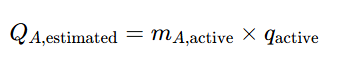
- mₐ,active: active material mass loading, g/cm²
- Q_active: respond specific capacity, mAh/g
If loading unit is mg/cm²:
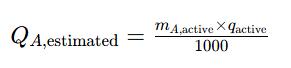
This value is only a design estimate. Electrochemical verification under target loading and operating conditions is mandatory.
2. Areal Capacity vs Coating Mass Loading
These are separate core parameters.
| Parameter | Meaning | Typical Unit |
|---|---|---|
| Dry coating mass loading | Total mass of dry coating per unit area (excluding foil) | mg/cm² |
| Active-material mass loading | Active material mass per unit coated area | mg/cm² |
| Areal capacity | Charge capacity per unit electrode area | mAh/cm² |
| Coating bulk density | Dry coating mass divided by coating volume (including pores) | g/cm³ |
| Coating thickness | Coating layer thickness, exclude current collector | μm |
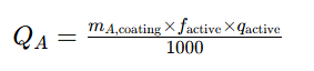
Dry coating contains active material, binder, conductive additives and other retained solid components.

f_active = active material mass fraction (decimal).
Combined formula (coating loading in mg/cm²):
Avoid ambiguous term “areal density”. Reports may refer to single coating side, double sides combined or foil-included value.
3. Areal Capacity Calculation Examples
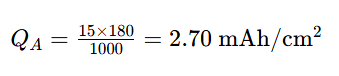
Example A: Known active material loading
Active material loading: 15 mg/cm²; usable specific capacity:180 mAh/g
Example B: Known total dry coating loading
Dry coating loading:20 mg/cm²; active fraction:95%; usable specific capacity:180 mAh/g

Mistake alert: Never treat full coating mass as pure active material; it will overestimate capacity.
CANRD Electrode Reference Examples
| Electrode Model | Dry Coating Loading | Active-Material Fraction | Listed Specific Capacity | Calculated Areal Capacity |
|---|---|---|---|---|
| NCM811 SY33 | 9.20 mg/cm² | 94.5% | 188 mAh/g | 1.63 mAh/cm² |
| NCM811 SY34 | 21.50 mg/cm² | 94.5% | 188 mAh/g | 3.82 mAh/cm² |
| Graphite SM02 | 5.80 mg/cm² | 95.7% | 340 mAh/g | 1.89 mAh/cm² |
Calculations match nominal values after rounding. These calculated values are product-specific nominal estimates only, not universal chemistry benchmarks or matched cathode-anode pairs. Consistent arithmetic does not replace electrochemical validation. Verify specs, coating convention and test conditions before cell assembly.
4. Single-Sided vs Double-Sided Electrodes: Prevent Double-Counting Error
Suppose each coating face of a double-sided electrode delivers 3.0 mAh/cm². For a 100 cm² foil area:
- One face: ~300 mAh
- Two faces total: ~600 mAh (if both coating layers are fully utilized)
Two valid reporting conventions:
- 3.0 mAh/cm² per coating face
- 6.0 mAh/cm² per foil footprint (both sides combined)
Always clarify which convention you use.
For an electrode-side capacity estimate, sum the participating coating faces of that electrode polarity only. Do not add cathode and anode capacities together to obtain full-cell capacity.
When calculating, define clearly: area = electrode disc area or coated area. Keep consistent for comparison.
5. How High Areal Capacity Improves Cell Energy Density
Simplified capacity balance:
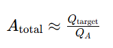
A_total is the summed participating coating-face area of one electrode polarity, using a consistent usable-capacity basis. This remains an electrode-side estimate; final full-cell capacity is further constrained by electrode balancing, active lithium inventory and operating voltage range.
Example target: 3 Ah
- At 3 mAh/cm²: ~1000 cm² coating area
- At 6 mAh/cm²: ~500 cm² coating area
Higher loading electrodes reduce required area for current collectors and separators, which is the core benefit.
Key limitations:
- Less coating area does not linearly reduce sheet quantity
- Pouch/can packaging mass does not automatically drop
- Electrolyte demand and mechanical tolerance change
- Controlled trade-offs in voltage or active material utilization may still yield net energy density gains
Current collectors and separators are vital functional components, not disposable dead volume.
6. Does Higher Areal Capacity Always Mean Thicker Electrodes?
No. Areal capacity rises via:
- Higher active material mass loading
- Higher usable specific capacity
- Higher active material mass fraction (without performance drop)
- Better utilization of existing coating
If chemistry, formulation and bulk density stay constant, higher loading increases coating thickness:
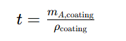
Example: 20 mg/cm² coating, bulk density 3.2 g/cm³

Foil thickness excluded.
Calendering reduces thickness at approximately unchanged mass loading; always verify post-calendering dimensions and areal mass. It modifies porosity, particle contact and electrode microstructure, changing accessible capacity.
Increasing coating thickness alone does not inherently increase diffusion length within unchanged particles.
7. Core Trade-offs for High-Loading Electrodes
Ionic transport in porous coating
Thicker coating increases ion transport path length. Pore tortuosity, pore connectivity, electrolyte conductivity and reaction uniformity become critical.
Electronic conduction
High loading requires robust conductive networks through coating thickness. Adding conductive additives helps but reduces active material fraction. Optimize via testing.
Electrolyte wetting & distribution
Thick electrodes are harder to fully wet. Evaluate filling process, soak time, pore structure, trapped gas and electrolyte dosage together. Adding electrolyte alone does not reliably resolve poor wetting; first identify the limiting cause.
Coating, drying & mechanical integrity
High loading raises risks: drying cracks, poor adhesion, residual solvent/moisture, thickness variation, damage during calendering, slitting or winding. These are process risks, not unavoidable defects.
Manufacturing cost
Less coating area may cut raw material and coating cost. But slower drying, higher scrap rate and low yield can offset savings. Evaluate cost by delivered energy per qualified cell, not coating area.
8. Pair C-Rate with Areal Current Density
At fixed C-rate:
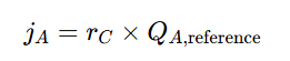
- j_A: areal current density, mA/cm²
- r_C: C-rate, h⁻¹
- Qₐ,reference: areal capacity used to set test current
| Reference Areal Capacity | Applied Areal Current Density @1C |
|---|---|
| 2 mAh/cm² | 2 mA/cm² |
| 4 mAh/cm² | 4 mA/cm² |
| 6 mAh/cm² | 6 mA/cm² |
High loading electrodes at identical C-rate run at higher areal current density. Always report both parameters and clarify whether current is calculated from theoretical, nominal or measured capacity. Where relevant, compare both matched C-rate and matched areal current density.
9. Target Areal Capacity for LFP, NMC and Graphite
There is no universal benchmark value. Valid comparison requires full context:
- Single-side / double-side reporting
- Calculated vs measured capacity
- Half-cell / full-cell setup
- Voltage window, charge direction, current, temperature, cycle number
- Electrode density, thickness and slurry formulation
Set targets by application priorities:
| Development Priority | Core Design Focus |
|---|---|
| High power / fast charge | Open pore structure, low polarization, high charge acceptance |
| High energy | Minimize inactive components while preserving usable capacity & voltage |
| Long cycle life | Mechanical stability, stable interfaces, controlled expansion |
| Mass manufacturing | Consistent loading, drying performance, handling and yield |
Lab-scale high areal capacity is not automatically a commercial production target.
10. Cathode-Anode Matching: N/P Ratio
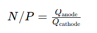
With equal electrode facing area:
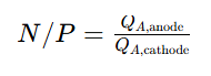
Define the reversible-capacity basis and the electrode potential windows versus Li/Li⁺ used for the calculation.
Example: anode 3.3 mAh/cm², cathode 3.0 mAh/cm² → N/P=1.10. This is just calculation, not a universal recommended value.
Account for usable voltage window, reversible capacity, first-cycle irreversible loss, manufacturing tolerance and electrode overlap.
Anode overhang should not be counted as equivalent to directly facing anode capacity in a simple local N/P calculation.
Even acceptable average N/P does not eliminate local lithium plating risk. Charging speed, temperature, local loading, alignment and ion transport also matter.
11. Practical Workflow for Areal Capacity Development
- Define cell specs: Target capacity, energy, power, charge rate, temperature range, cycle life and dimensions
- Set reporting standard: Coating side definition, dry loading, active fraction, specific capacity basis and area definition
- Prepare an electrode loading series: Keep material/formulation unchanged, increase loading stepwise, measure thickness and density
- Evaluate processability: Slurry property, loading uniformity, drying quality, adhesion, resistance and handling
- Electrochemical characterization: Test areal capacity, specific capacity, voltage profile, rate capability and impedance
- Validate matched full cells: Half cells screen electrodes; full cells verify N/P balance, formation loss, electrolyte limit and practical performance
- Recalculate energy density & cost: Use measured discharge energy, include foil, separator, electrolyte, tabs, packaging and mechanical allowance
CANRD design principle: Evaluate loading, density, N/P ratio and manufacturability together.
Conclusion
Areal capacity bridges material properties and practical electrode utilization. Higher mass loading reduces electrode area required for a fixed target capacity, but expected energy-density gains must be validated with measured utilization, voltage retention, cycle durability and production yield. Controlled performance trade-offs can still deliver net positive energy-density outcomes.
The best target is a validated operating window supported by consistent loading measurement, electrochemical testing and full-cell verification.
For CANRD electrode custom & material evaluation, prepare your chemistry, formulation, target coating loading, single/double-sided format, thickness/density target and test conditions to build your electrode and cell validation plan.
FAQ
Q1: What formula calculates electrode areal capacity?
A: Design estimate = active material loading(g/cm²) × usable specific capacity(mAh/g). Measured value = total capacity ÷ defined electrode area.
Q2: Is coating mass loading equal to active material loading?
A: No. Dry coating includes binder and conductive additives. Multiply coating loading by active mass fraction to get active material loading.
Q3: Does double-sided electrode deliver double areal capacity?
A: Depends on reporting convention. Capacity summed over two sides per foil footprint differs from per-coating-face capacity. Always state the definition.
Q4: Does higher areal capacity guarantee higher cell energy density?
A: No. Lower inactive component mass helps, but material utilization, voltage, electrolyte and packaging determine final cell energy density.
Q5: Does calendering increase areal capacity?
A: With unchanged loading, calendering adds no active material. It can increase or decrease accessible capacity, depending on the resulting contact and pore structure.
Q6: Why high loading electrodes underperform at same C-rate?
A: Higher loading creates higher areal current density. Longer ion transport path inside thick coating and microstructure differences increase polarization.
Q7: What is ideal areal capacity for EV batteries?
A: No universal number. Select and validate against cell energy, fast charge, temperature, cycle life and manufacturing requirements.
Related Products & Services
Use Canrd products and R&D services to turn battery knowledge into practical experiments.
Coin Cell Case
ProductCoin cell cases for validating materials and electrochemical concepts from the article.
Use coin cell cases in your next test →Sodium Electrolyte
CategoryElectrolytes for sodium-ion battery research, compatibility tests, and cell validation.
Shop sodium electrolyte for validation →Cell Fabrication
ServiceGet support building dry cells, assembled cells, or custom formats for R&D validation.
Request cell fabrication support →Experimental Materials
CategoryBrowse materials for follow-up experiments, benchmarking, and product development.
Browse experimental battery materials →
