contact@canrd.com
 +86 18928276992
 Battery Conductive Additives Guide: Carbon Black vs CNT vs Graphite — Which to Choose?
1. Introduction: Core Purpose of Conductive Additives
- Cathode materials (LFP, NCM, LCO, LNMO): Semiconductors or insulators with extremely low electronic conductivity
- Graphite anodes: Basal-plane conductivity is sufficient, yet particle contact gaps expand during lithiation/delithiation, triggering rising polarization and capacity loss
2. How Conductive Additives Improve Electrode Performance (Dual Transport Mechanism)
2.1 Core Functional Impacts of Conductive Carbons
- Reduce ohmic and electrochemical polarization, unlock full reversible discharge capacity and stabilize voltage platforms
- Boost fast charge / discharge rate capability across low and high temperature operating windows
- Preserve particle-to-particle contact during repeated volume swing to extend long-term cycle retention
- Mitigate local overpolarization conditions that lead to lithium plating (additives alone cannot fully eliminate dendrite formation)
- Specific flake or fibrous carbons can enhance coating flexibility and calendering compaction depending on morphology
- Improve coating adhesion between active powder and current collector in optimized composite systems
2.2 Electronic & Indirect Ionic Transport Mechanism
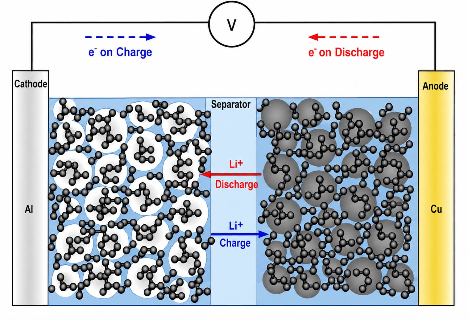
- Electronic Conductive Pathways Conductive carbons build short-range coating layers around individual active particles and long-range bridging networks between distant grains, lowering bulk electrode resistance.Without continuous carbon pathways, electron transport energy barriers surge, suppressing lithium insertion react
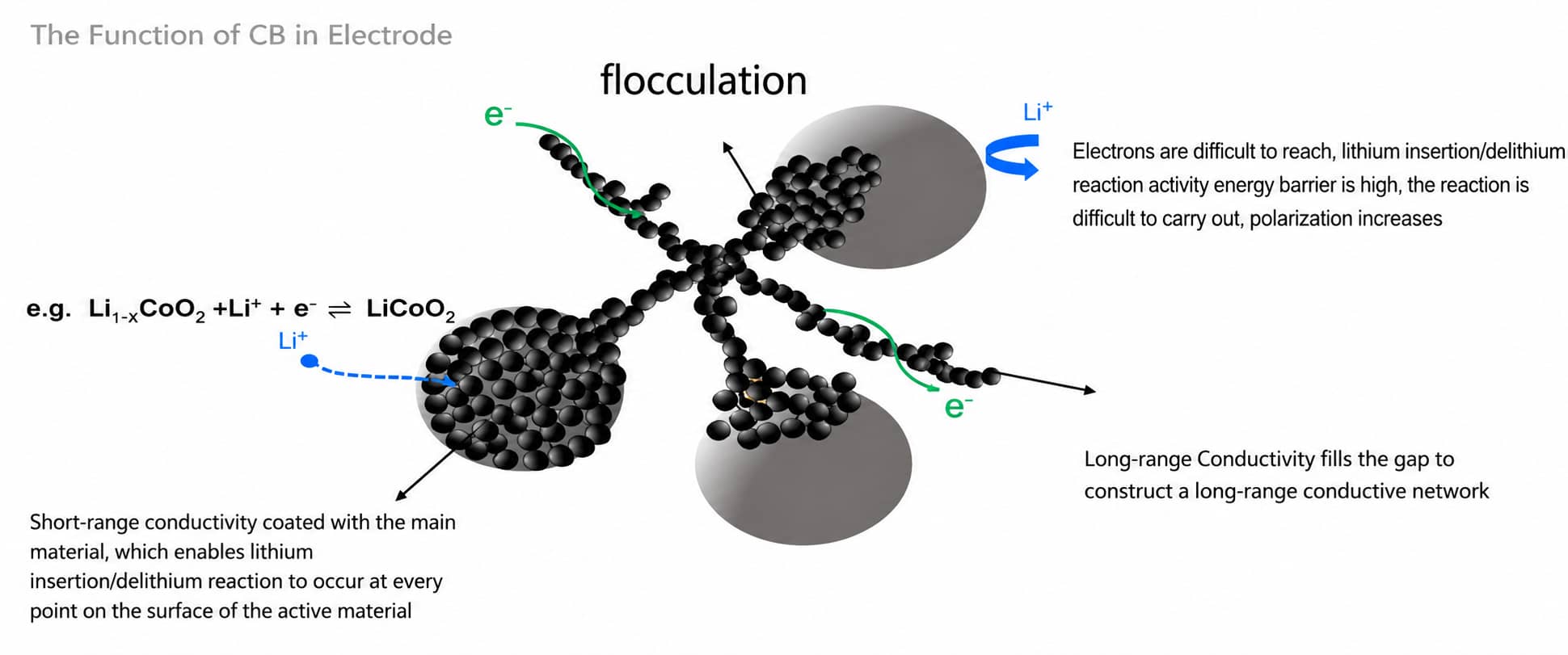
2.Indirect Ionic Transport Support
Porous carbon structures trap and retain carbonate electrolyte, expanding triple-phase reaction interfaces. This indirectly reduces electrochemical polarization, though conductive additives themselves do not conduct lithium ions.
3. Full Comparison of Commercial Conductive Carbon Types
| Material Category | Representative Grades | Typical Morphology | BET Range | Core Advantages | Key Processing Risks |
|---|---|---|---|---|---|
| Standard Carbon Black | Super P (SP) | Branched chain nano aggregates | ~62 m²/g | Balanced cost & dispersibility, universal baseline | Requires moderate loading to form full networks |
| Acetylene Black (AB) | Acetylene-derived carbon black | Spherical nano particles | ~80 m² | Ultra-low metal impurity content | Longer high-shear mixing required for uniform dispersion |
| High-BET Hollow Carbon | SAC 350G | Hollow open nano spheres | ~770 m²/g | Superior electrolyte retention, low loading threshold | Severe self-agglomeration; dry premixing & dispersant mandatory |
| Flake Cathode Graphite | KS6 | Thick rigid micro flakes | ~20 m²/g | Boost cathode compaction density | Limited short-range conductive coverage |
| Flake Anode Graphite | SFG6 | Thin high-graphitization flakes | ~20 m²/g | Matches spherical graphite anodes, improves initial efficiency | Not suitable for low-conductivity cathodes |
| VGCF Carbon Fiber | VGCF | Solid micron fiber | ~13 m²/g | Excellent thermal homogenization at high rates | Uneven fiber distribution without segmented feeding |
| Multi-Wall CNT | MWCNT | Hollow nano tubes | 180–250 m²/g | Ultra-long-range crosslinked conductive skeletons | Strong van der Waals entanglement, hard to deagglomerate |
3.1 Zero-Dimensional Carbon Black Detailed Introduction
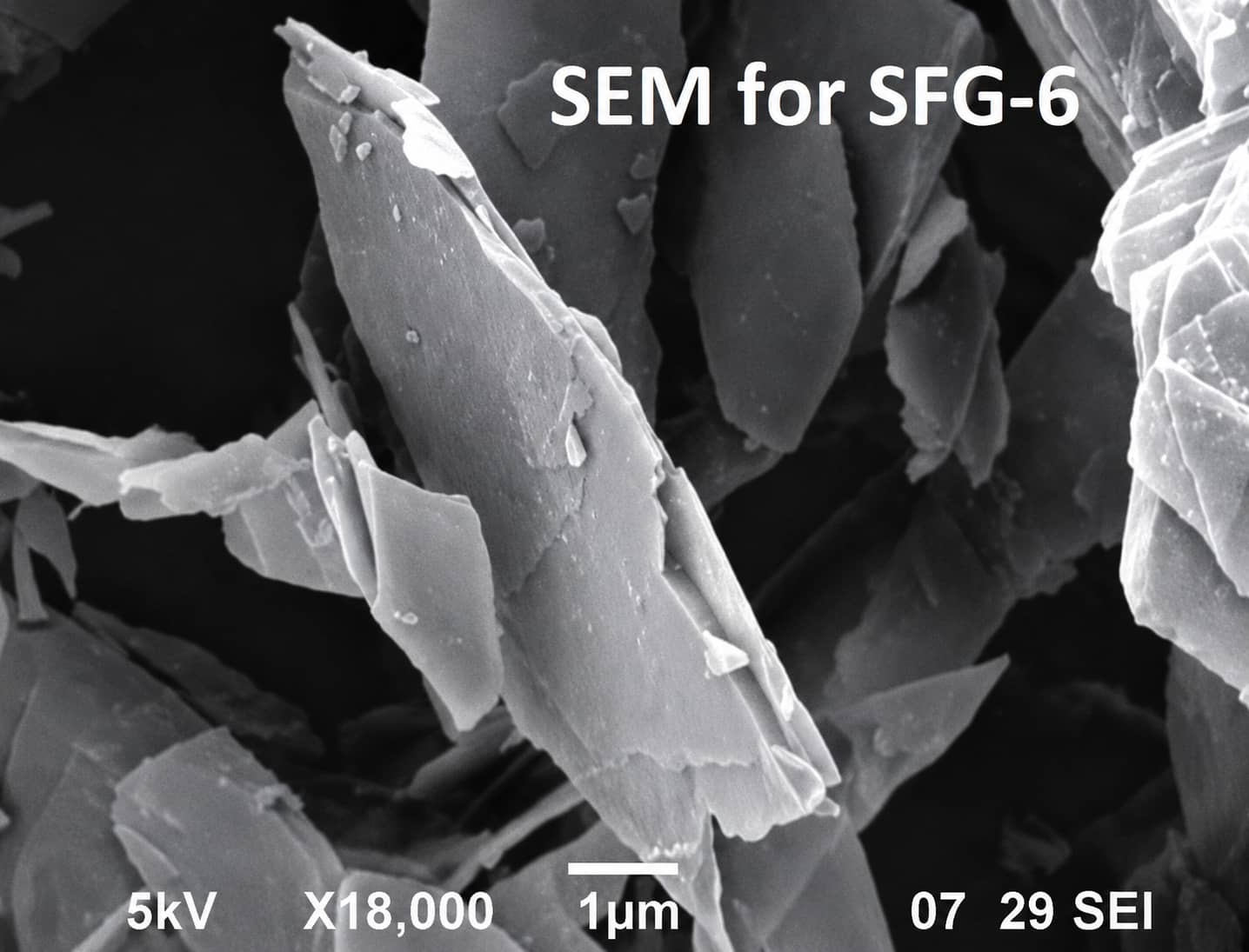
3.2 Two-Dimensional Flake Graphite (SEM Micrographs)
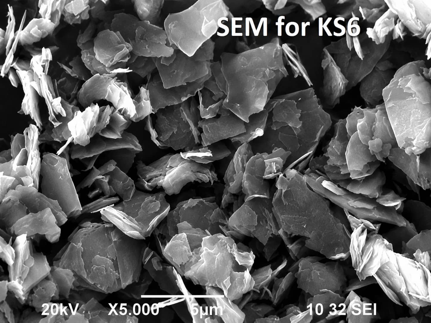
- KS Series: Thick rigid flakes that raise cathode compactness after calendering; low irreversible capacity loss, not recommended for graphite anodes
- SFG Series: Thin highly graphitized flakes perfectly matched with spherical anode graphite particles, improving first-cycle coulombic efficiency and electrode packing density
3.3 One-Dimensional CNT & VGCF Fibrous Conductive Additives
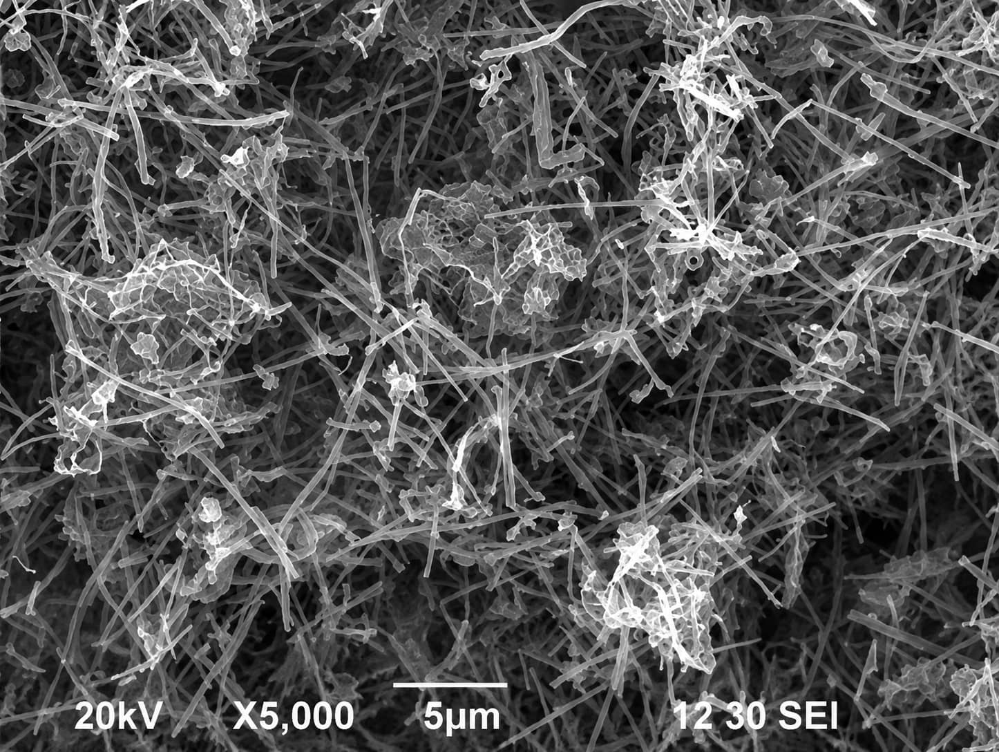
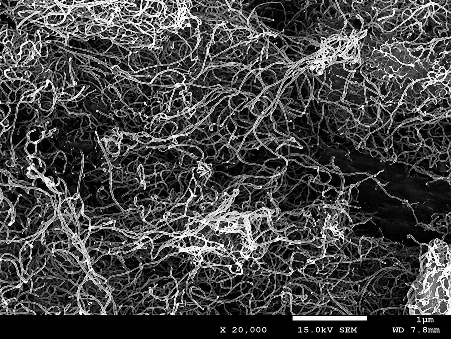

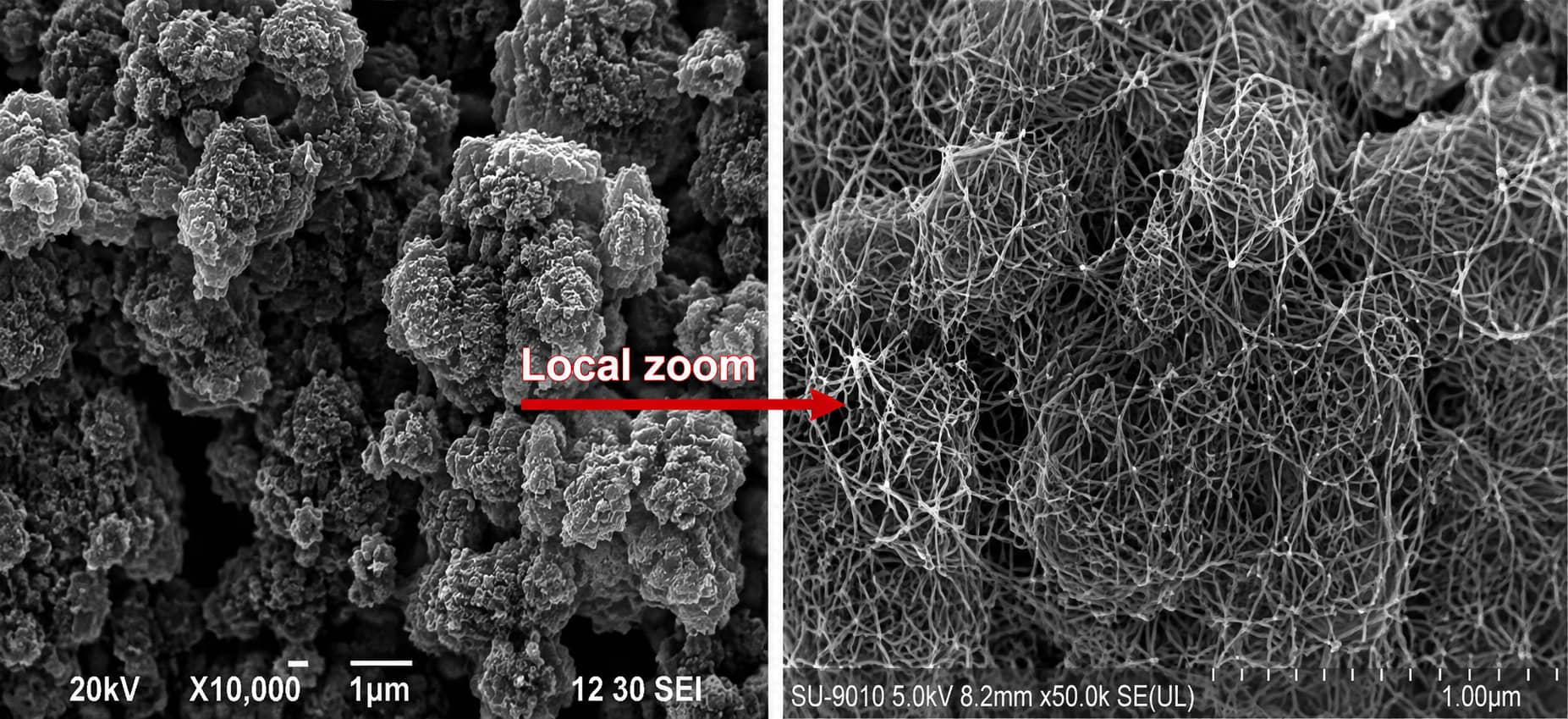
- Combined electronic and thermal conductivity homogenizes temperature distribution under fast discharge, avoiding local hotspots
- Interpenetrating fiber networks maintain particle contact during silicon particle expansion and contraction (fibers do not eliminate silicon’s intrinsic volume change)
- Improve electrode ductility to reduce cracking after repeated cycling Major processing limitation: Nano tubes easily tangle during mixing; pre-dispersed conductive slurry is the preferred industrial solution.
4. How to Select Conductive Additives for Different Electrode Systems
| Electrode System | Main Performance Limitation | Recommended Conductive Network Strategy |
|---|---|---|
| LFP Cathode | Intrinsically low electronic conductivity | Baseline Super P low-dose MWCNT hybrid |
| NCM/LCO Thick Cathode | Through-thickness resistance rise after calendering | Super P KS6 flake graphite composite |
| LNMO High-Voltage Cathode | Severe polarization under high-rate discharge | Super P VGCF fiber for thermal balance |
| Spherical Graphite Anode | Low initial coulombic efficiency | Super P SFG6 thin flake graphite |
| Silicon-Carbon Anode | Broken conductive networks after Si expansion | MWCNT / VGCF primary hybrid system |
5. How Much Conductive Carbon Should You Add? (Dosage Tradeoffs NCM523 Case Study)
5.1 Key Dosage Tradeoff Principles
- Occupies electrode volume/mass and lowers overall cell energy density
- Raises total slurry binder and solvent demand
- Expands electrode surface area, aggravating irreversible capacity loss on formation
5.2 Historical NCM523 Cathode Formulation Case
| Material | Function | Dry Weight Ratio | Actual Feeding Mass |
|---|---|---|---|
| NCM523 Active Powder | Capacity source | 96 wt% | 261.1 g |
| Super P Conductive Carbon | Point conductive network | 2 wt% | 5.4 g |
| PVDF Homopolymer Binder | Coating adhesion | 2 wt% | |
| NMP Solvent | Slurry carrier | N/A | 128.0 g |
Corresponding Dispersing Process for Super P
- Dissolve PVDF powder in NMP, stir 10 mins at 400 rpm then 4 hours at 650 rpm to form transparent homogeneous glue
- Add Super P into binder solution, low-speed pre-wet (400 rpm /10 mins), then high-shear dispersion (650 rpm / 2 hours) to break carbon agglomerates
- Introduce NCM523 powder and repeat kneading & dispersion steps
- Adjust viscosity with extra NMP, vacuum degas to eliminate bubbles before coating
Critical Reminder
6. Root Causes & Fixes for Nano-Carbon Agglomeration in Slurries
Primary Agglomeration Triggers
- High-BET carbon black / MWCNT have strong inter-particle van der Waals forces
- Improves powder feeding sequence (all nano-carbon added at once without pre-wetting)
- Insufficient mixing shear force or short dispersion duration
- Mismatched binder-solvent system with poor carbon wettability
Standard Optimization Solutions
- Segmented powder feeding: Disperse nano conductive carbon separately before introducing high-BET active materials
- Deploy carbon-specific dispersants compatible with PVDF (cathode) / CMC-SBR (anode)
- Adopt pre-manufactured dispersed conductive slurry to skip in-line high-shear mixing risks
- Implement water circulation cooling during long dispersion to avoid temperature-induced re-agglomeration
- Avoid blindly extending mixing time; excessive shear and temperature rise will alter slurry rheology and destroy pre-formed conductive networks
7. Troubleshooting High Electrode Resistance (Evidence-Based Diagnosis Flow)
- Slurry stage inspection: Test fineness, viscosity and sedimentation to confirm full carbon dispersion
- Electrode stage testing: Measure surface sheet resistance, cross-section SEM to check carbon coating uniformity
- Cell stage validation: Run EIS and rate discharge tests to distinguish bulk electrode resistance vs electrolyte/interface polarization
| Defect Phenomenon | Potential Multi-Source Causes | Targeted Optimization |
|---|---|---|
| Consistently high full-cell resistance | Incomplete conductive network OR poor carbon dispersion | Add low-dose CNT hybrid OR extend vacuum high-shear mixing to verified dispersion endpoint |
| Localized coating high impedance spots | CNT/carbon black agglomerates on coating surface | Optimize feeding order add dedicated dispersant; use fineness test for routine QC, reserve SEM/TEM for advanced analysis |
| Resistance rises sharply after calendering | Lack of flake graphite planar conductive paths | Integrate KS6 (cathode) / SFG6 (anode) into formulation |
| Silicon anode rapid capacity decay | Conductive network fractures during silicon volume swing | Replace partial Super P with MWCNT/VGCF hybrid |
8. Complete Validation Workflow for New Conductive Formulas
- Slurry QC: Check wettability, dispersion fineness, viscosity stability and bubble content
- Electrode manufacturing: Assess coating uniformity, peel strength and maximum compaction density
- Coin half-cell screening: Measure intrinsic capacity, rate performance and initial coulombic efficiency
- Pouch full-cell verification: Match real N/P ratios to test cycle retention, low-temperature discharge and thermal behavior
- Prototype module aging: Verify batch consistency under long-term storage and cycling abuse conditions
9. Carbon-Coated Aluminum & Copper Foil Supporting Technology
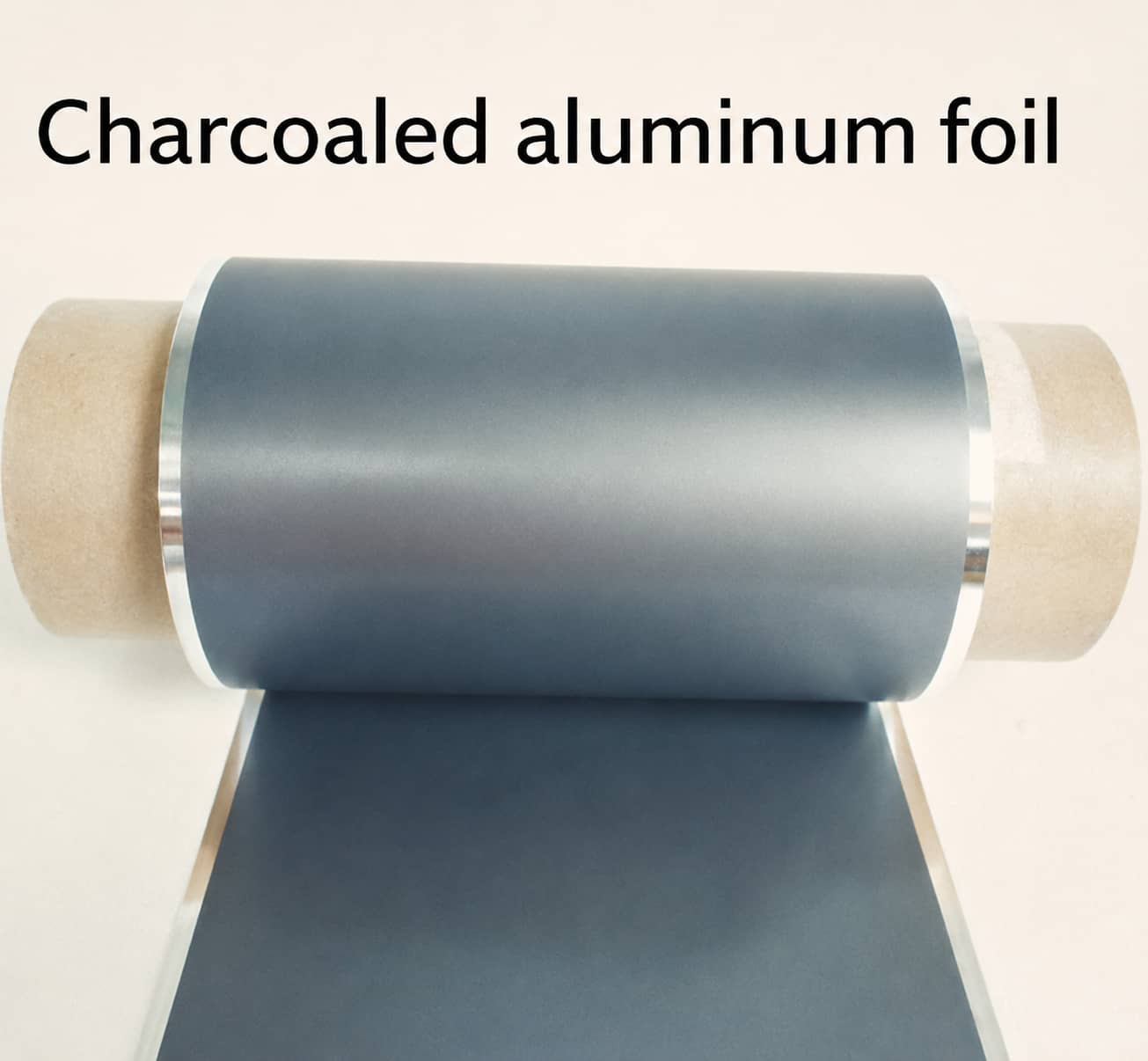
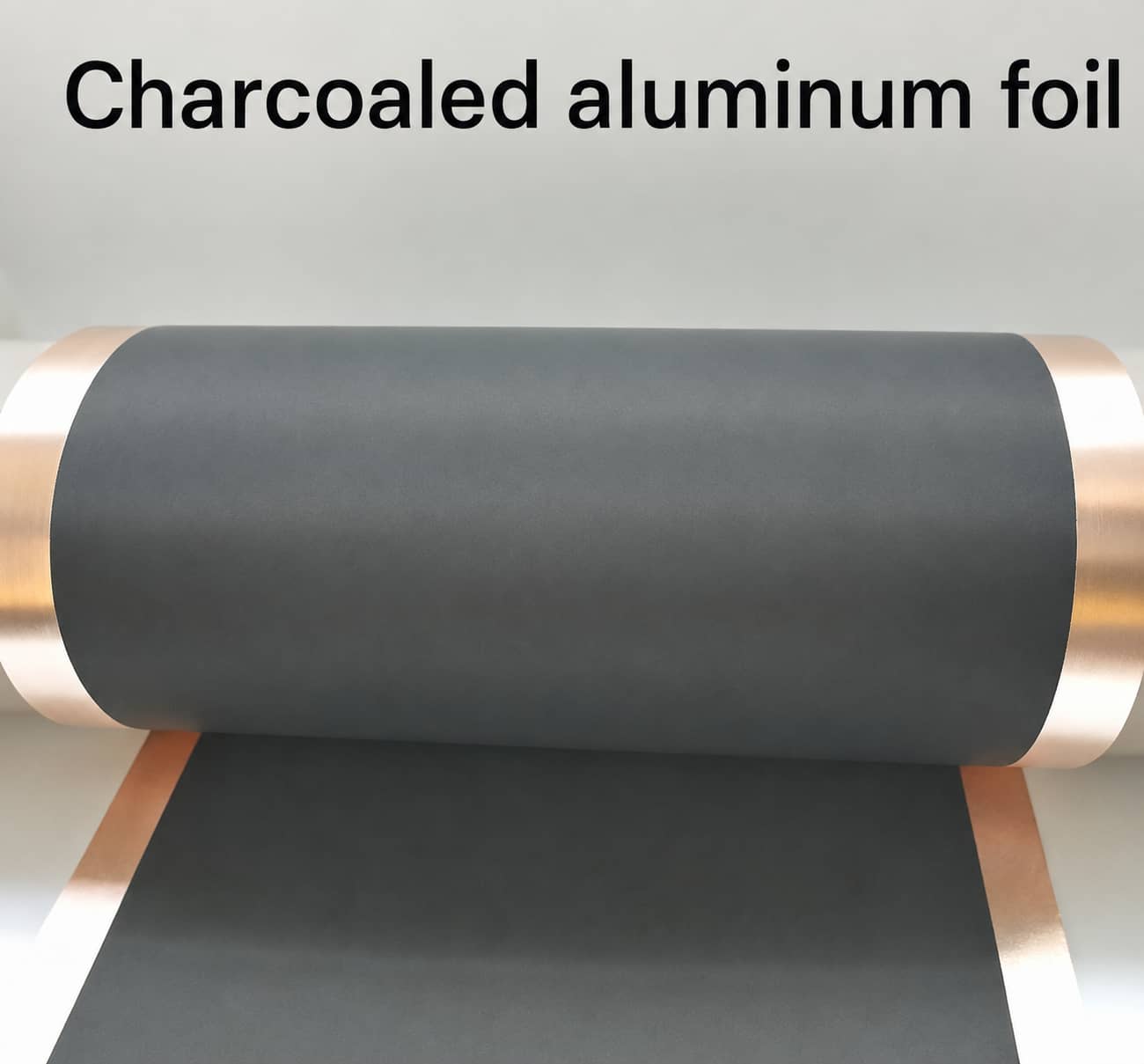
- Enhance adhesion between coating layer and metal substrate, reducing delamination risk during thousands of cycles, with actual performance dependent on coating formula
- Lower interfacial contact resistance between active powder and current collector, especially beneficial for high-compression thick cathode electrodes
10. Emerging Conductive Additive Development Directions
10.1 Low-Cost Mass Production Route
10.2 High-Energy Density Nano-Carbon Systems
10.3 Long-Cycle Hybrid Conductive Composites
10.4 Silicon Anode Specialized Conductive Skeletons
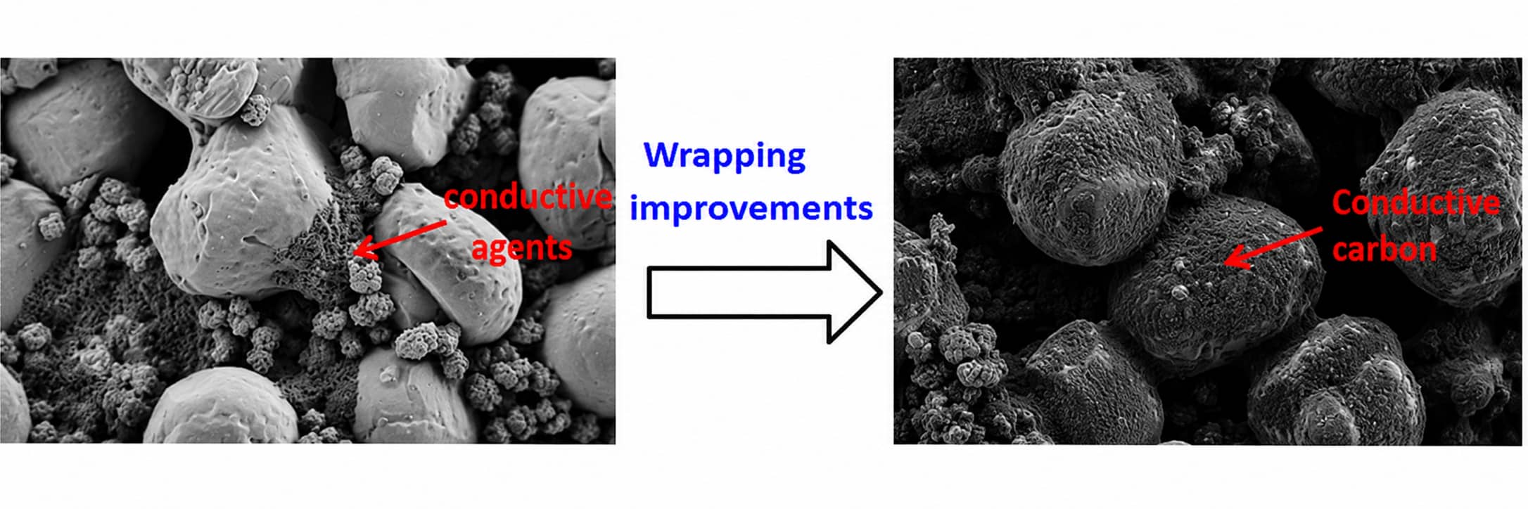
10.5 Surface Functionalized Conductive Carbon
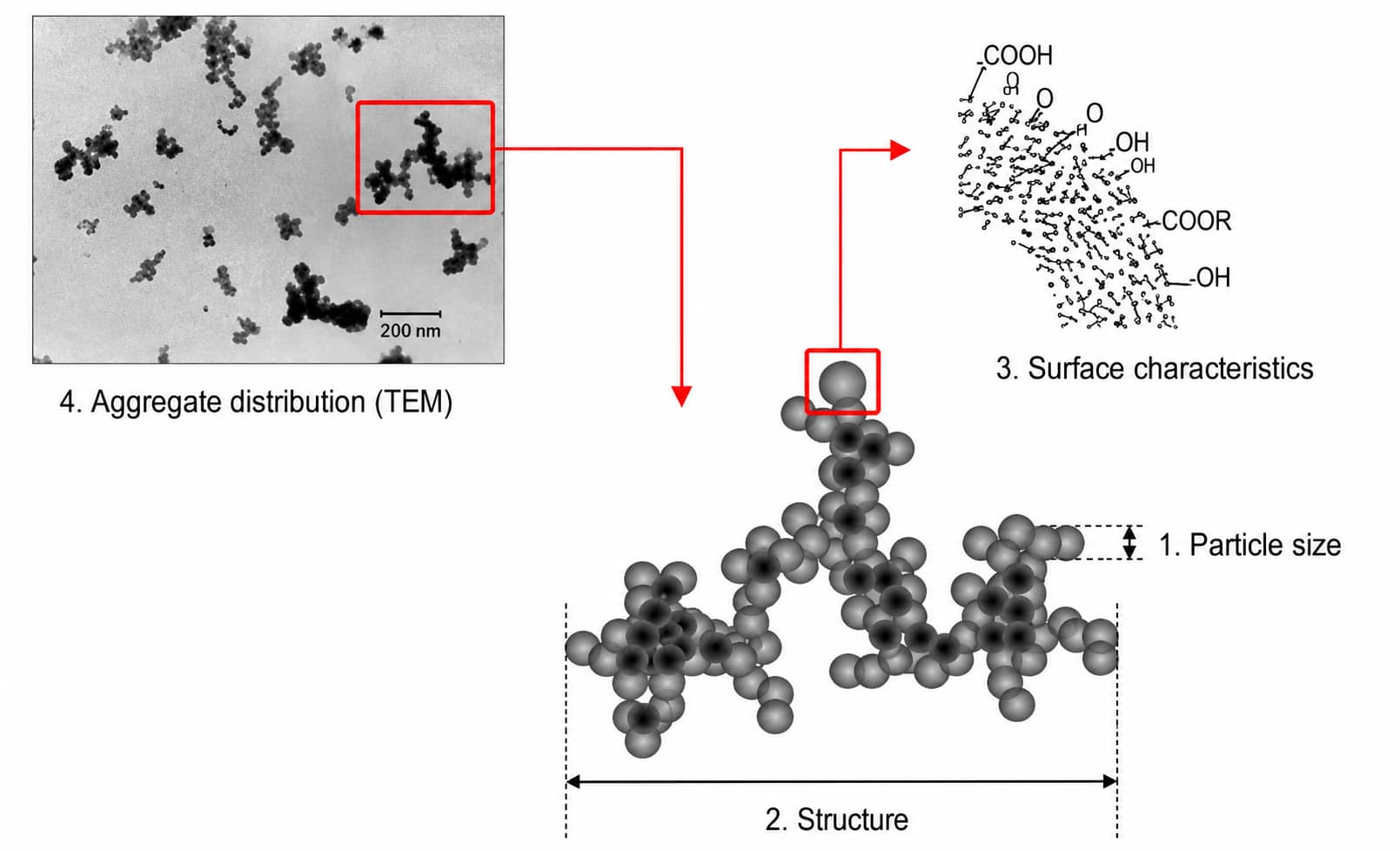
10.6 Conductive Coated Current Collectors
11. Frequently Asked Questions
Q1 What is the core difference between KS6 and SFG6 flake graphite?
Q2 Can pure Super P satisfy high-rate discharge battery requirements?
Q3 What conductive additive combination works best for LFP cathodes?
Q4 Do silicon-carbon anodes require mandatory CNT addition?
Q5 What advantages does carbon-coated aluminum foil provide for high-nickel cathodes?
Conclusion
Choosing the right conductive additive for lithium-ion battery electrodes requires balancing conductivity, dispersion, electrode structure and cell performance. Carbon black, conductive graphite, CNT and VGCF each provide different advantages in building short- and long-range conductive networks.
The goal is not to maximize conductive additive content, but to find the minimum effective dosage that delivers low resistance, good rate capability and stable cycling without sacrificing energy density or processability. Final formulations should be validated through slurry dispersion, electrode resistance and full-cell testing, rather than copied from a fixed recipe.
Related Products & Services
Use Canrd products and R&D services to turn battery knowledge into practical experiments.
Coin Cell Case
ProductCoin cell cases for validating materials and electrochemical concepts from the article.
Use coin cell cases in your next test →Sodium Electrolyte
CategoryElectrolytes for sodium-ion battery research, compatibility tests, and cell validation.
Shop sodium electrolyte for validation →Cell Fabrication
ServiceGet support building dry cells, assembled cells, or custom formats for R&D validation.
Request cell fabrication support →Experimental Materials
CategoryBrowse materials for follow-up experiments, benchmarking, and product development.
Browse experimental battery materials →