

 contact@canrd.com
 +86 18928276992
 Home/Resources/Knowledge/Battery Material/Why Does PVDF Binder Turn Brown? Causes, Usability & High-Nickel NCM Slurry Gelation
Why Does PVDF Binder Turn Brown? Causes, Usability & High-Nickel NCM Slurry Gelation
Canrd August 14, 2026 223
Introduction
PVDF binder discoloration, unexpected gelation during high-nickel slurry mixing, and poor manufacturability of high-performance novel binders are three of the most frequent production pain points for lithium-ion battery R&D engineers and slurry technicians. This guide draws entirely on CANRD’s 2019 internal full-cell manufacturing training data to break down root chemical mechanisms, share original lab test data, and deliver actionable troubleshooting workflows.
All basic binder definitions, classification, raw material selection rules and standard performance testing methods are covered in our primary resource Battery Binder Complete Selection Guide (Part I): PVDF, CMC/SBR Testing & Material Matching.
Condensed Binder Core Overview
Battery adhesives serve two core roles within electrode slurries: rheology control and inter-particle adhesion. They adjust slurry viscosity to prevent active material sedimentation and guarantee uniform dispersion during mixing; post-coating, they bind active powders, conductive carbon and metal current collectors together to resist cracking during calendaring.
Commercial mainstream binders include NMP-soluble PVDF for cathodes and LTO anodes, water-based CMC SBR composite systems for graphite anodes, and PTFE for aqueous supercapacitors. Emerging experimental binders cover lithiated PAA, PAN, PI, PAI, PMMA, PVA and sodium alginate, each designed to address specific material pain points such as large volume variation in silicon-containing anodes. This SEM micrograph visualizes the adhesive network wrapping active particles, conductive carbon and the metal current collector, the core structural foundation of electrode bonding covered in Part I.
1. Why Does PVDF Binder NMP Solution Turn Yellow or Brown?
1.1 Visual Comparison of Normal & Discolored PVDF Glue
In mass mixing workshops, clear transparent PVDF-NMP stock solutions often turn amber, tan or dark reddish-brown after storage or high-shear mixing.
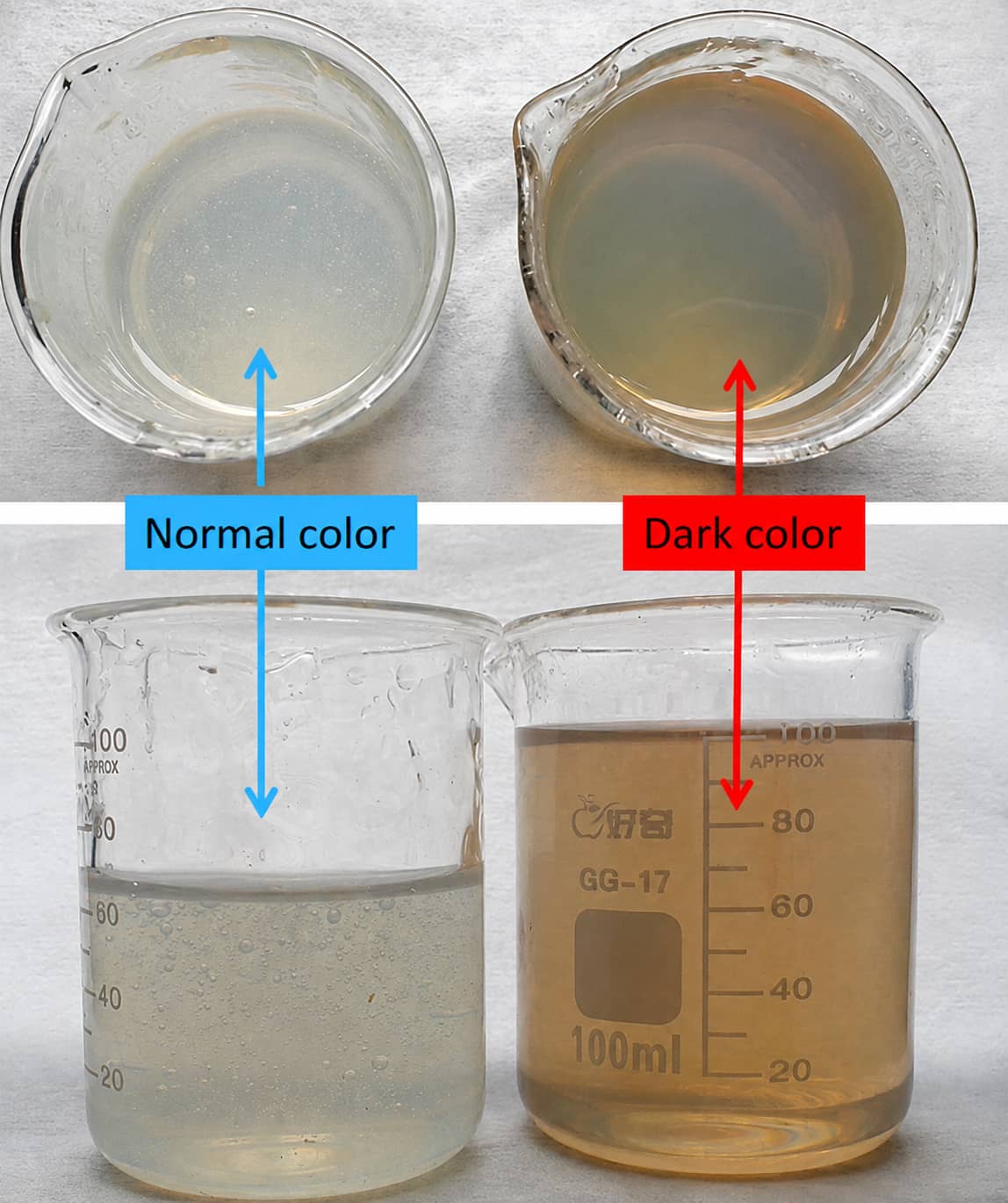
Left samples = qualified pale transparent PVDF glue; Right samples = aged, discolored PVDF binder liquid.
1.2 Root Chemical Mechanism: PVDF Dehydrofluorination & Conjugated Double Bond Formation
Discoloration stems from bimolecular elimination (de-HF) reactions triggered by alkaline free ammonia in low-purity NMP or sustained high temperatures:
- Alkaline free ammonia attacks C-H and C-F bonds on PVDF polymer chains
- HF molecules detach, forming continuous C=C conjugated double bonds along the backbone
- Extended π-π conjugated systems shift light absorption into the visible spectrum, darkening solution color
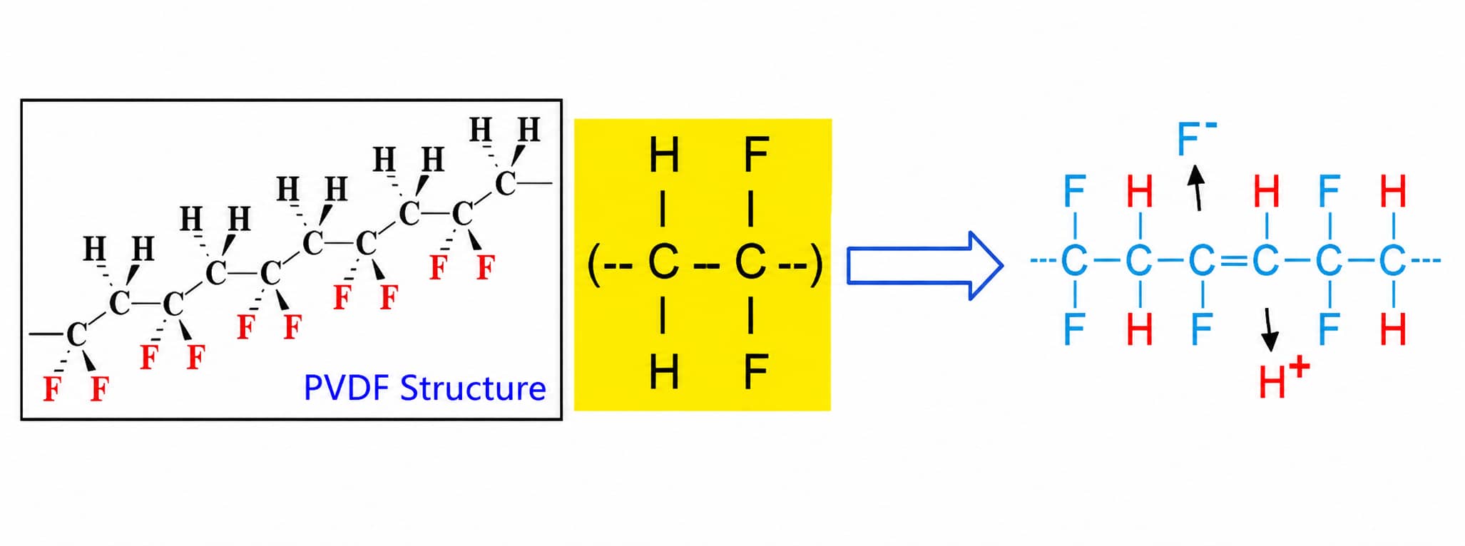
Equipment effectively defined directly briefly; however: higher levels (lower) → higher temperature (lower temperature) → Integrity (Italy) → Lunch (Daily Reserve), whose parents need accurate transparency and but whose parents cannot.
1.3 Key Accelerating Factors Confirmed by Internal Lab Tests
- NMP purity: Low-purity solvent carries higher free ammonia content, drastically speeding discoloration
- Storage temperature: Higher temperatures amplify absorbance peak intensity and color depth
- PVDF grade: Homopolymer PVDF discolors far faster than high-molecular-weight copolymer modified PVDF
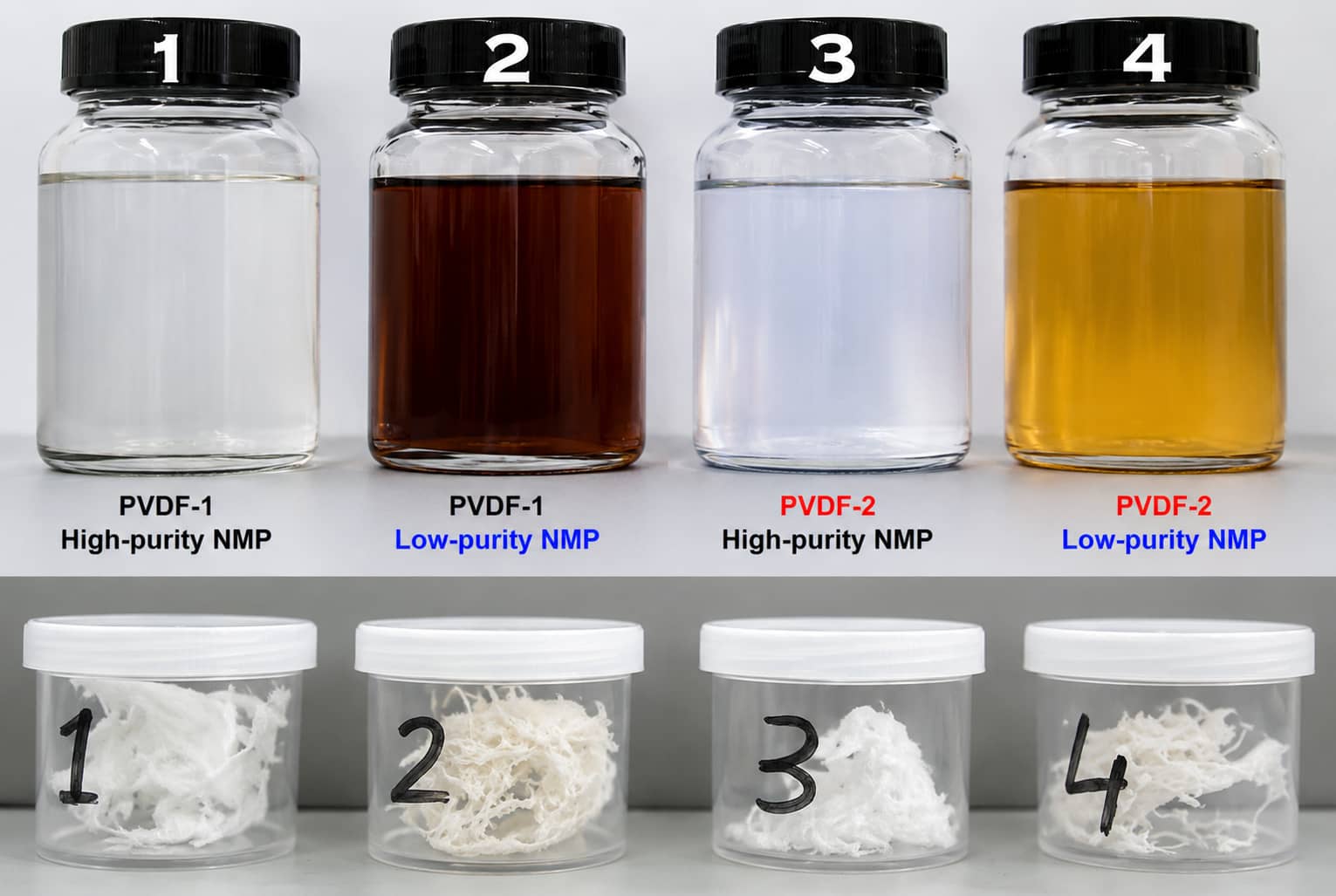
Test setup: 5wt% PVDF in NMP; Group1/3 = high-purity NMP, Group2/4 = low-purity NMP; Solef 1013 (PVDF-1) shows more severe darkening than Solef 6020 copolymer PVDF.
2. Can Discolored PVDF Binder Solution Still Be Used?
2.1 Pre-Use Decision Workflow
- Observe only color shift with no precipitation/gelation → First test slurry viscosity & stability
- Coating trial to measure cathode adhesion strength
- Cross-check NMP batch purity and glue storage temperature history
- If all core process indicators meet project standards, proceed with small cell validation
- Critical Rule: Do not reject batches solely based on visual discoloration
2.2 CANRD Case Study: PVDF Discoloration Lab Test Dataset
This original internal experiment tracks adhesion, UV absorbance and molecular weight across 2–day storage temperatures (23°C / 40°C / 60°C / 100°C)
| Test Item | Historical CANRD Observation | Practical Engineering Meaning |
|---|---|---|
| Cathode Adhesion Test | No statistically significant peel strength gap between normal and discolored PVDF electrodes | Color shift does not directly degrade foil-coating bonding performance |
| UV Absorbance Scan | Absorption peaks at 227/273/314nm rise sharply with temperature elevation | Higher heat accelerates conjugated double bond generation |
| GPC Molecular Weight Analysis | MW range held steady at 221,000–230,000 across all temperature groups | No large-scale PVDF polymer chain degradation occurs during discoloration |
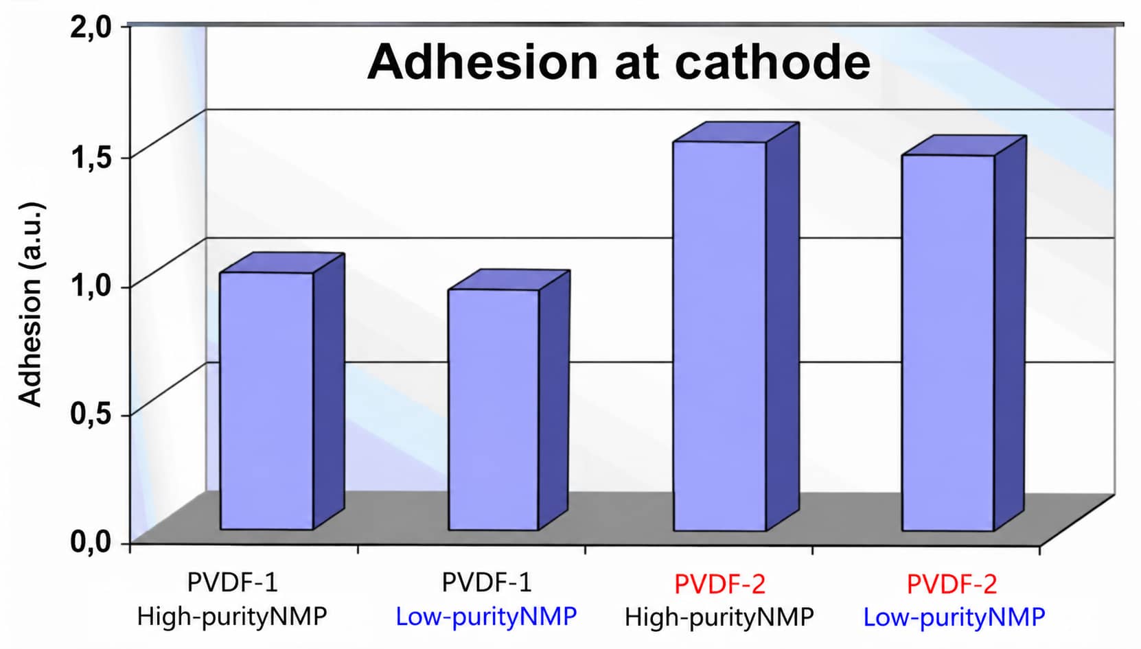
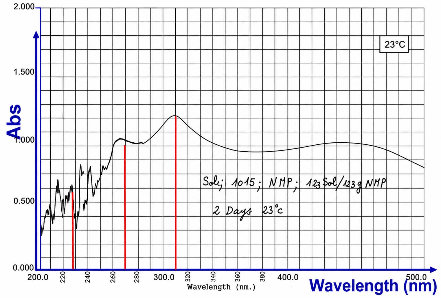
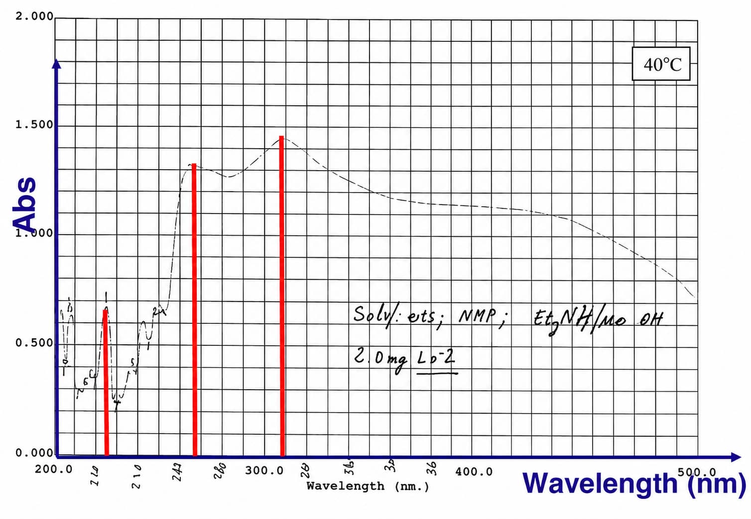
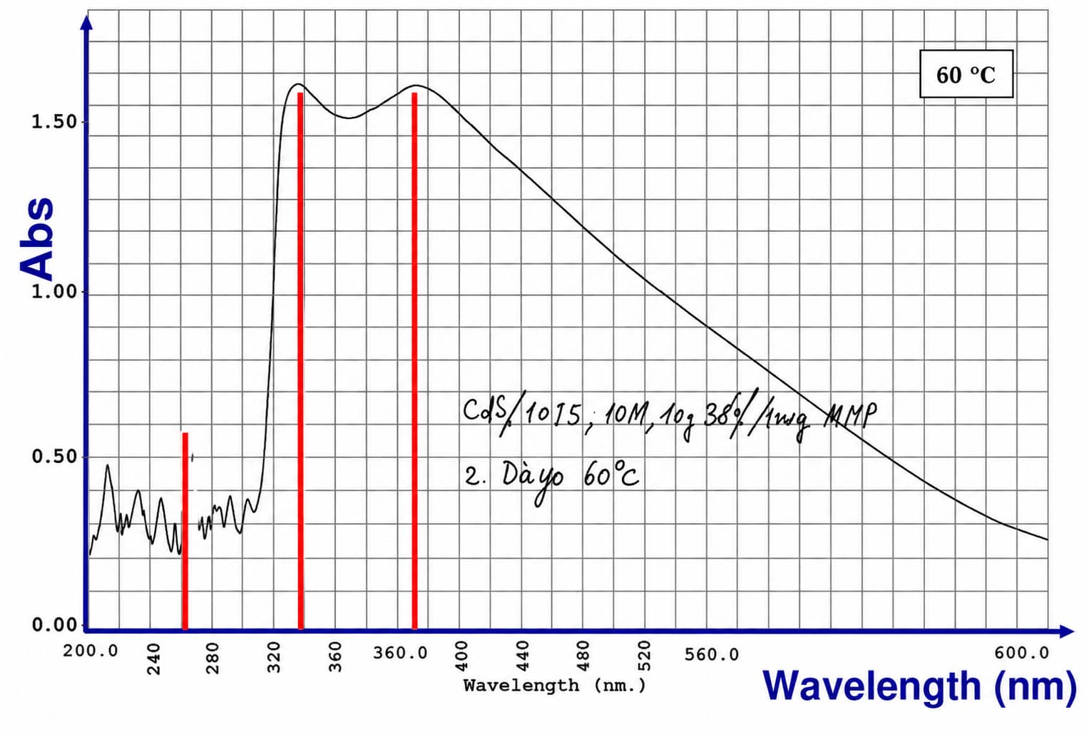
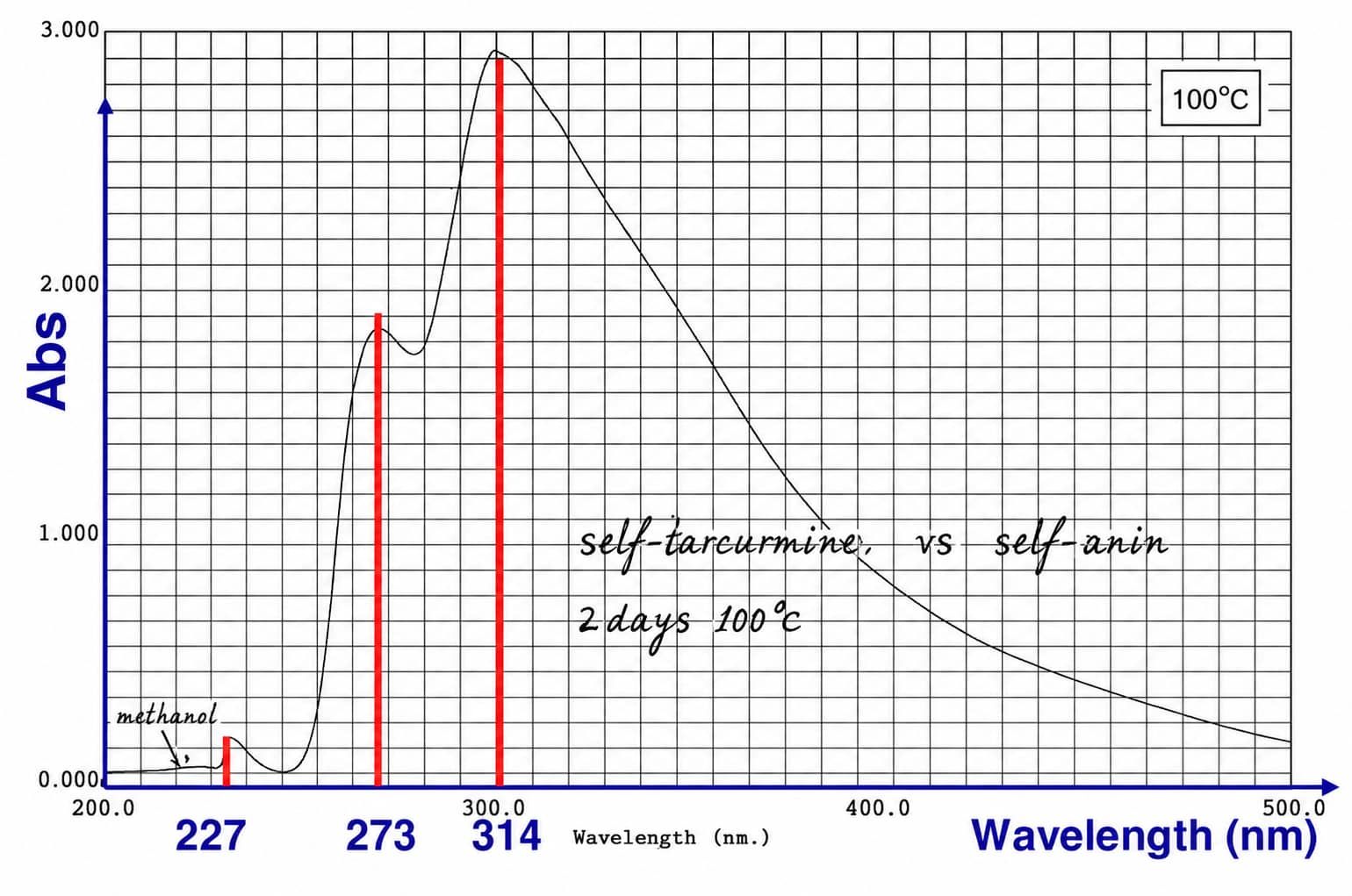
Adhesion test chart confirms negligible difference between high/low-purity NMP groups for both Solef PVDF grades; UV spectra clearly demonstrate rising absorbance at elevated temperatures without measurable molecular weight breakdown.
2.3 Process Mitigation to Reduce PVDF Discoloration Frequency
- Utilize high-purity NMP with controlled free ammonia levels for binder preparation
- Maintain low bulk solution temperature during high-speed planetary mixing (avoid sustained heat buildup)
- Select high-molecular-weight copolymer modified PVDF grades for improved color stability
- Prepare PVDF glue on-demand; avoid long-term sealed high-temperature storage of finished binder stock
3. Why Does High-Nickel NCM811 / NCA Slurry Gel With PVDF?
3.1 Three Root Trigger Factors (From CANRD 2019 Training)
- Elevated residual alkali on high-nickel active material surfaces: The reference training example recorded slurry pH near 11.75 for unwashed NCM811 powder
- Conventional homopolymer PVDF vulnerability to de-HF reactions in alkaline environments, forming crosslinked conjugated networks that induce irreversible gelation
- Excess moisture from raw materials or uncontrolled mixing workshop humidity, amplifying alkaline PVDF degradation reactions
Note: RH <10% for cathode mixing lines is listed as a historical engineering reference benchmark, not a universal global manufacturing standard.
3.2 Step-by-Step High-Nickel Slurry Gelation Troubleshooting Flow
- Check residual alkalinity of incoming NCM/NCA cathode powder batches
- Mitigation: Source cathode materials with supplier-implemented surface washing treatments to lower baseline pH
- Verify PVDF binder formulation grade
- Mitigation: Swap conventional homopolymer PVDF for anti-gelation copolymer modified PVDF to suppress large π-π conjugated crosslinking
- Audit moisture control across the full mixing workflow
- Mitigation: Seal raw material storage tanks, monitor workshop relative humidity
- Review mixing temperature and total high-shear residence time
- Mitigation: Install circulation cooling on mixing equipment to limit sustained heat exposure that accelerates PVDF de-HF
4. What Scale-Up Problems Did CANRD Observe With Novel Binders?
The following manufacturing defects and limitations are historical observations from 2019 binder pilot line trials; they do not constitute a definitive statement that PAA/PI chemistries cannot be optimized for full commercialization in 2026.
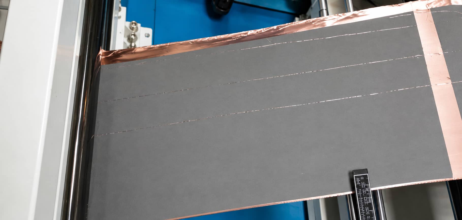
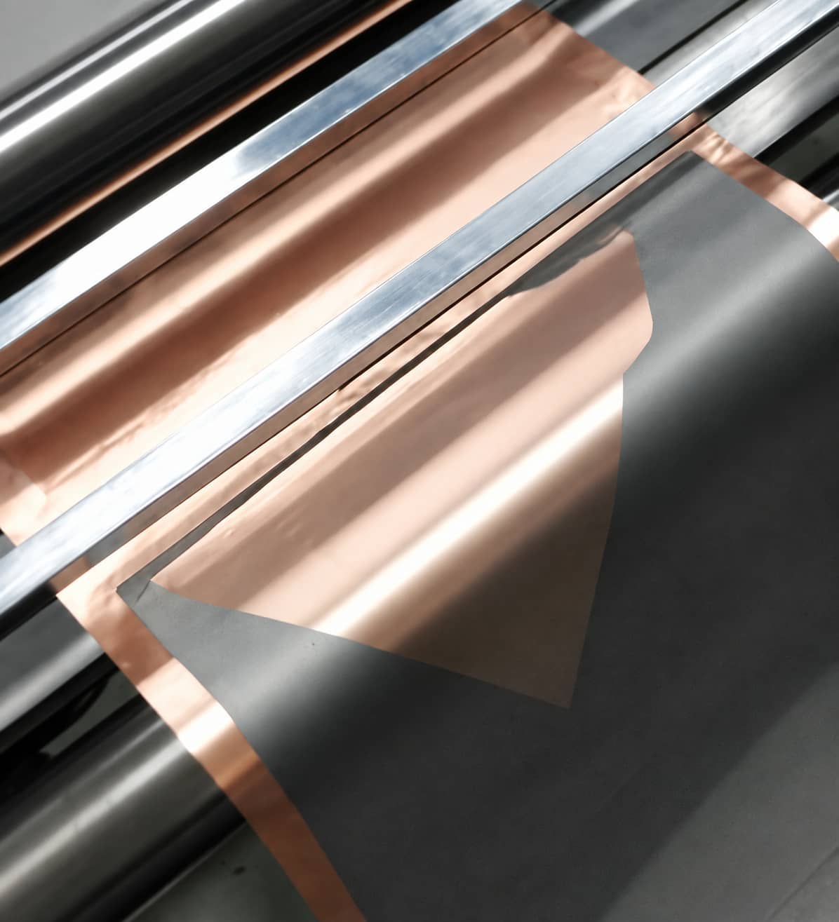
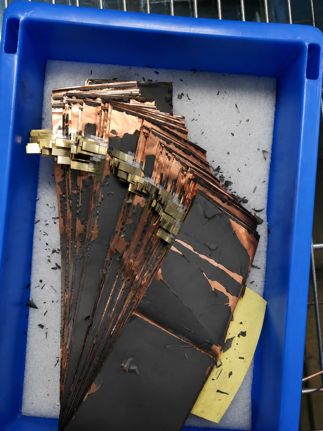
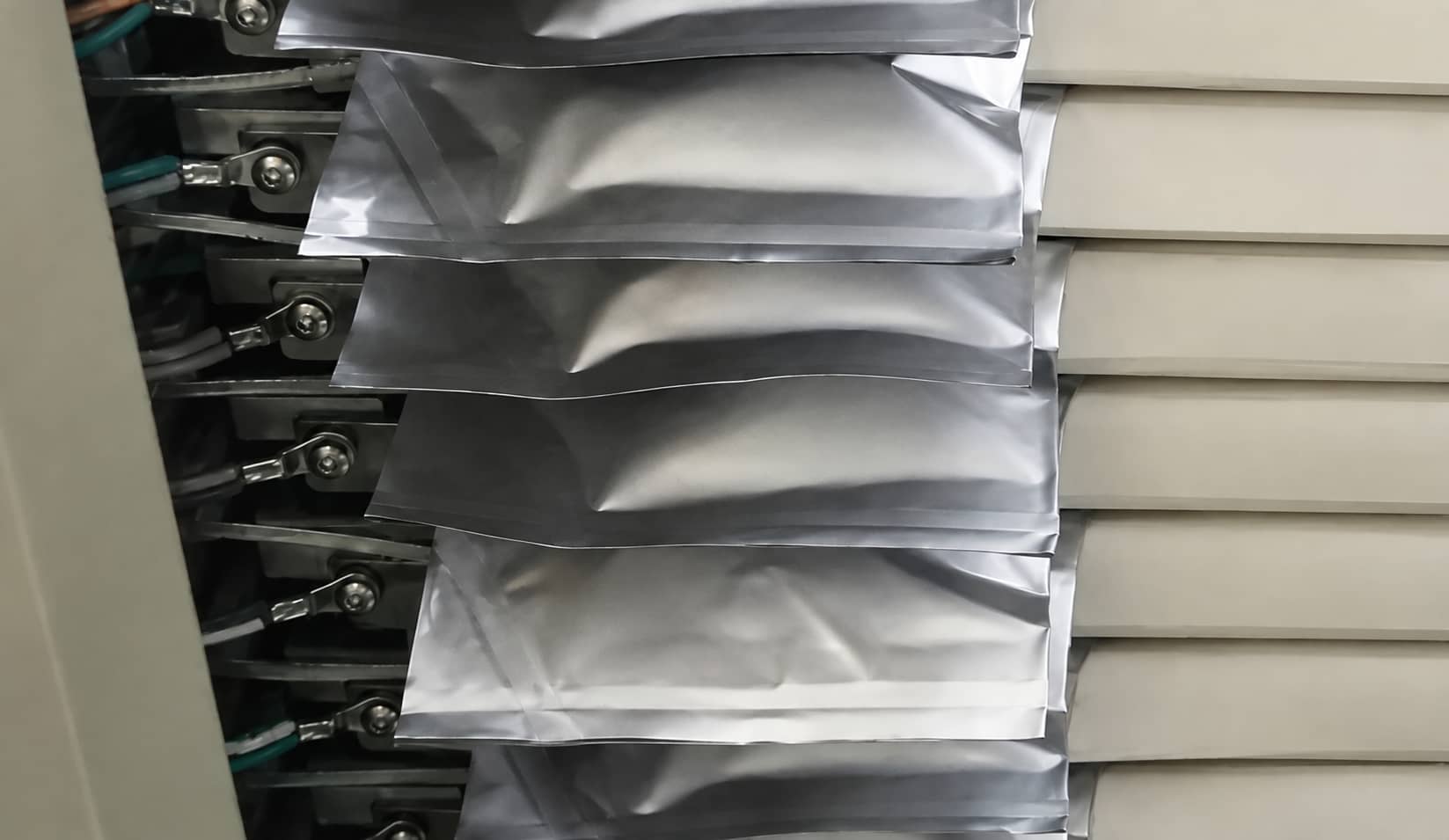
All photos capture real mid-scale production failures observed when testing lithiated PAA binders for silicon-carbon anodes.
4.1 Lithiated PAA for Silicon-Containing Anodes
Documented Performance Advantages in Lab Coin Cells
- High tensile strength to preserve electrode integrity during large silicon volume fluctuations
- -COOLi functional groups boost ionic conductivity and fast-charging rate capability
Recorded Pilot Scale-Up Barriers
- High coating brittleness leads to curling and cracking post-drying
- Strong hygroscopic carboxyl groups cause persistent roller adhesion during cold calendering
- Severe powder loss during electrode slitting and sheet processing
- Trapped residual moisture is difficult to fully bake out, triggering excessive gas evolution during cell formation
4.2 Polyimide (PI) High-Safety Binder
Documented Lab Advantages
- Imide molecular structure delivers high tensile resilience to accommodate electrode dimensional shifts during cycling
- Elevated thermal decomposition threshold improves cell thermal safety
Recorded Pilot Scale-Up Barriers
- Mandatory ~250°C high-temperature polycondensation bake after coating, drastically increasing line energy costs and equipment modification requirements
- Material rigidity outweighs flexibility; deformed electrodes cannot recover flat geometry, damaging foil-coating interfacial contact
- Lone electron pairs on imide groups irreversibly consume lithium during initial intercalation, reducing first-cycle Coulombic efficiency
- Premium raw material pricing limits cost competitiveness for mass EV production
5. Why Does a Battery Electrode Lose Adhesion? Core Adhesion Mechanisms Translated for Battery Production
General adhesive textbook theory is simplified below to focus exclusively on lithium-ion electrode foil-coating bonding pain points, aligned with CANRD training slide content.
5.1 Four Core Interfacial Bonding Drivers
- Wettability Requirement
The binder solution must fully infiltrate micro-roughness on active particle and metal foil surfaces without trapped air bubbles; incomplete wetting creates stress concentration points that cause peeling under cycling load. Low binder viscosity and small liquid-solid contact angles speed uniform infiltration.
- Mechanical Interlocking Effect
Micro-pores on etched/roughened aluminum/copper foil trap solidified binder matrix, creating physical anchor points that boost peel strength far above smooth untreated current collectors.
- Intermolecular Adsorption Forces
Primary long-term adhesion comes from hydrogen bonds and van der Waals intermolecular forces between binder functional groups and active material surfaces; complete molecular contact relies on full slurry wetting.
- Chemical Bonding Interactions
Modified specialty binders can form weak ionic or covalent bonds with metal foil or powder surface functional groups for enhanced cycle-long bonding stability.
5.2 Physical & Chemical Factors That Degrade Electrode Adhesion
Physical Influencing Factors
Current collector surface roughness & pretreatment, binder coating thickness, residual internal drying stress, shear/peel load during calendaring, slurry additive migration
Chemical Influencing Factors
Material polarity matching, binder molecular weight, side-chain functional group design, slurry pH, crosslinking density, solvent/plasticizer content, conductive carbon filler loading
6. Standard Validation Process for New Binder Formulations Before Scale-Up
- Small lab slurry preparation to test viscosity, dispersion stability and visual appearance
- Mini coating trial to inspect surface defects, roller compatibility and post-drying brittleness
- Electrode peel strength testing to quantify baseline adhesion performance
- Full cell formation and cycling testing to monitor gas generation, capacity fade and rate performance
- Extended high-temperature storage validation to assess long-term binder-electrolyte compatibility
FAQ
Q1 If PVDF glue turns amber during storage, can I directly use it for EV cathode mass production?
A Color change alone is not a batch rejection trigger per CANRD’s historical test data. You must first test slurry viscosity, run a coating adhesion trial, cross-check NMP purity and storage temperature history, then complete small full-cell validation before releasing the batch to mass lines.
Q2 What is the fastest corrective action for sudden gelation of NCM811 slurry during mixing?
A Immediately halt high-shear stirring. Audit four core variables: residual alkali of cathode powder, PVDF binder grade, workshop moisture levels, and mixing heat buildup. Long-term fixes require switching to anti-gel copolymer PVDF and sourcing low-residual-alkali high-nickel material.
Q3 Why can’t lithiated PAA fully replace CMC SBR for commercial silicon-carbon anode mass production?
A Historical pilot trials documented critical manufacturability flaws including coating cracking, calender sticking, powder shedding and formation gas evolution. Lab electrochemical performance does not translate directly to stable large-scale production without extensive formulation and process optimization.
Q4 What binder is recommended for lithium titanate (LTO) anodes?
A Conventional PVDF dissolved in NMP solvent; strict moisture control across all mixing steps is required to prevent unwanted side reactions with LTO powder.
Q5 What key indicators should I test before preparing large-volume PVDF glue batches?
A NMP free ammonia purity, PVDF molecular weight grade, mixer cooling capacity, ambient storage temperature and workshop relative humidity.
Conclusion
This Part II troubleshooting guide leverages CANRD’s exclusive 2019 internal lab and pilot line data to resolve three industry-leading binder failure modes: PVDF discoloration chemistry & usability rules, high-nickel slurry gelation root causes, and real-world scale-up limitations of high-performance novel PAA/PI binders. All foundational binder knowledge, material matching tables and standard testing workflows are consolidated in Battery Binder Complete Selection Guide (Part I): PVDF, CMC/SBR Testing & Material Matching.
Previous
PVDF vs CMC/SBR vs P...Related Products & Services
Use Canrd products and R&D services to turn battery knowledge into practical experiments.
Coin Cell Case
ProductCoin cell cases for validating materials and electrochemical concepts from the article.
Use coin cell cases in your next test →Sodium Electrolyte
CategoryElectrolytes for sodium-ion battery research, compatibility tests, and cell validation.
Shop sodium electrolyte for validation →Cell Fabrication
ServiceGet support building dry cells, assembled cells, or custom formats for R&D validation.
Request cell fabrication support →Experimental Materials
CategoryBrowse materials for follow-up experiments, benchmarking, and product development.
Browse experimental battery materials →
