



Lithium-Ion Battery Cathode Materials: Types, Selection Guide and Performance Comparison
1. Introduction: Match Cathode Materials to Your Battery Development Goals
| Primary Development Target | Recommended Cathode Family | Key Validation Focus Areas |
|---|---|---|
| Long cycle life, low cost, grid energy storage | LFP | High loading conductive network, compaction density, low-temperature discharge |
| High energy density passenger EVs | NCM / NCA | Residual alkali content, moisture control, thermal stability, gassing behavior |
| High volumetric energy consumer electronics (phones/laptops) | LCO | High-voltage cycling stability, calendering adhesion, thermal runaway risk |
| High power output, high-voltage battery packs | Spinel LMO / LNMO | Manganese dissolution, high-temperature impedance rise, electrolyte oxidation |
| Ultra-high capacity lab R&D | Li-rich Mn-based solid solution | Initial coulombic efficiency, oxygen release, long-term voltage decay |
2. What Is a Lithium-Ion Cathode & Rocking-Chair Working Principle
2.1 Definition of Cathode Active Material
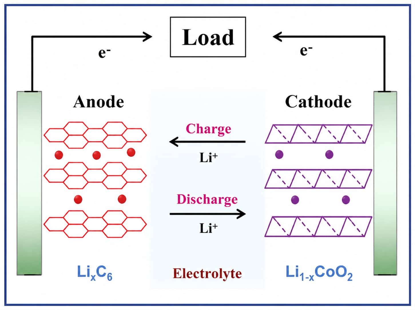
2.2 Rocking-Chair Electrochemical Mechanism
- Charging: External voltage drives Li⁺ to deintercalate from Li₁₋ₓCoO₂ cathode, migrate through EC/DEC carbonate electrolyte, and embed into graphite layers to form LiₓC₆; electrons flow externally from cathode to anode.
- Discharging: Li⁺ detaches from graphite anodes and returns to the cathode lattice to deliver power to external loads.
2.3 Full Cell Component Classification
Cathode Electrode Only Components
- Cathode active powder (Li-ion source)
- Conductive agents (carbon black, carbon nanotubes, electronic conductive network)
- PVDF binder & NMP solvent (adhesion for coating layers)
- Aluminum foil cathode current collector
General Full-Cell Components (Not Part of Cathode Slurry)
- Anode materials: graphite, silicon-carbon composites Silicon-Carbon vs Graphite Anode Guide
- Separator: microporous PP/PE multilayer polyolefin films (nonwoven fabrics for niche high-safety systems)
- Electrolyte: LiPF₆/LiAsF₆ dissolved carbonate solvent film-forming/flame retardant additives
- Packaging: aluminum plastic pouch film, aluminum/stainless steel hard shells
3. Standardized Cathode Material Selection Framework (8 Core Evaluation Metrics)
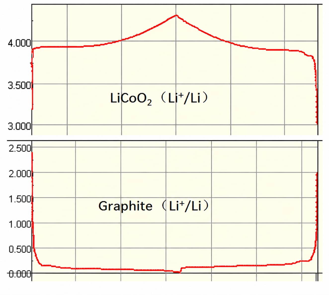
- Sufficient redox potential vs Li⁺/Li: Delivers high full-cell operating voltage to boost energy density. Usable voltage windows are constrained by both crystal stability and electrolyte oxidation limits.
- High reversible gravimetric capacity: Theoretical specific capacity calculated via Faraday’s law (corrected from the inaccurate formula in original training slides):
Q_th = nF / 3.6 = 26800n / M (mAh/g)
- n = moles of electrons transferred per mole active material
- F = 96485 C/mol (Faraday constant)
- M = molar mass of cathode material
- Mass m is excluded from theoretical specific capacity calculation; multiply by m only to get total capacity for a given powder weight.
- LiCoO₂: 273 mAh/g
- LiNiO₂: 274 mAh/g
- LiMn₂O₄: 148 mAh/g
- LiFePO₄: 170 mAh/g
- Minimal lattice distortion during cycling: Low structural degradation ensures long cycle retention
- Fast Li⁺ diffusion & high electronic conductivity: Supports high-rate fast charging without severe polarization
- Chemical inertness in carbonate electrolyte: Suppresses continuous side reactions during long cycling
- Scalable, low-cost raw material supply chain: Reduce reliance on scarce metals like cobalt
- Acceptable thermal stability: Mitigate thermal runaway and gassing risks under abuse conditions
- Compatible with industrial slurry & coating processes: Avoid unmanageable slurry defects (gelation, agglomeration)
4. Mainstream Cathode Types & Engineering Trade-Offs (3 Crystal Structure Families)
All commercial and R&D cathodes fall into three core crystal structures; the comparison table below summarizes balanced pros and cons without absolute overstatements:
4.1 Hexagonal Layered Oxides (LiCoO₂, NCM, NCA, Li-Rich Solid Solution)
- LCO (LiCoO₂)
Strengths: Stable flat discharge platform, excellent electronic conductivity, mature mass production, suitable for high-current dischargeLimitations: Cobalt supply constraints, limited overcharge tolerance, moderate thermal stability, higher environmental impactApplications: Premium consumer electronics (smartphones, notebooks)
- NCM Ternary (LiNiₓCoᵧMnzO₂, NCM111/523/622/811)
Strengths: Tunable energy density via nickel ratio, balanced cycle life, wide discharge voltage windowLimitations: Cost volatility tied to cobalt pricing, thermal stability declines as nickel content rises
- NCA (LiNiₓCoᵧAlzO₂)
Distinction from NCA: Aluminum replaces manganese in crystal lattice, forming an independent layered system (not a subset of NCM). Delivers higher gram capacity at equivalent nickel content but stricter moisture control requirements.
- Li-Rich Mn-Based Solid Solution (xLi₂MnO₃·(1-x)LiMO₂, M=Ni,Co,Mn)
Strengths: Ultra-high capacity (>250 mAh/g between 2–4.8 V), manganese-dominated low-cost raw materials, decent thermal stability, low heavy metal relianceLimitations: Severe long-term voltage fade, unstable lattice under wide voltage cycling, complex industrial synthesisIndustry milestone: BASF partnered with Argonne National Laboratory in 2009 to advance large-scale industrialization of Li-rich cathode technology
4.2 Spinel Structure Cathode (LiMn₂O₄/LNMO 5V Spinel)
- LMO (LiMn₂O₄): Low raw material cost, abundant manganese reserves, simple synthesis; suffers from manganese dissolution at elevated temperatures leading to capacity fade
- LNMO (LiNi₀.₅Mn₁.₅O₄): 5V high-voltage platform, pairs well with lithium titanate anodes for ultra-stable full-cell cycling; requires high-voltage resistant electrolyte matching to prevent solvent decomposition
4.3 Polyanionic Phosphate Cathode (LiFePO₄, LFP)
5. Critical Gap: Why Powder Data Cannot Represent Full-Cell Performance
Raw Cathode Powder → Slurry Formulation & Mixing → Calendered Cathode Electrode → Coin Half-Cell → Pouch Full-Cell → Prototype Module
Two Standard Evaluation Modes for Reliable Comparison
- Unified Benchmark Testing: All cathode powders tested under identical slurry solid content, coating loading, electrolyte and voltage windows to isolate intrinsic material differences. Ideal for rapid material screening.
- Material-Specific Optimized Testing: Tune binder ratio, conductive additive dosage and electrolyte formula for each cathode system to measure its maximum practical performance ceiling. Used for final product design validation.
Key Processing Factors That Suppress Theoretical Capacity
- Poor powder dispersion creates disconnected conductive networks and high internal resistance
- High-nickel residual alkali triggers slurry gelation, uneven coating thickness
- Excess calendering compaction induces electrode cracking and active material isolation
- Mismatched electrolyte formulations accelerate cathode-electrolyte interphase (CEI) degradation
6. Common Cathode Processing Defects: Diagnosis & Optimized Adjustment Logic
| Defect Phenomenon | Potential Root Hypotheses | Verification Testing | Multi-Dimensional Optimization Directions |
|---|---|---|---|
| LFP slurry severe agglomeration, poor dispersion | Nano-scale primary particles with high BET surface area, insufficient solvent wetting | Fineness test, SEM particle imaging, slurry rheology scan | Extend high-shear vacuum mixing time; moderately raise PVDF/conductive carbon dosage; optimize powder feeding sequence for gradual wetting |
| High-nickel ternary slurry gelation & excessive viscosity | High surface residual alkali, unmodified PVDF incompatibility, ambient moisture absorption | Powder pH/residual alkali test, comparative slurry with low-pH precursor, humidity-controlled mixing | Source low-pH high-nickel powder; switch to copolymer modified PVDF PVDF Cathode Binder Guide; strictly control glovebox moisture during slurry preparation |
| Low full-cell discharge capacity & low initial coulombic efficiency | Electrolyte formulation mismatched to cathode voltage window, poor CEI film formation | Side-by-side half-cell test with dedicated high-nickel/high-voltage electrolyte | Avoid universal anode electrolyte for high-nickel/LNMO cathodes; add film-forming additives matched to cathode operating range |
| Cathode cracking, peeling after high-compaction calendering | Insufficient binder adhesion, excessive coating surface density, smooth bare aluminum foil | Electrode peel strength test, cross-section SEM of calendered layers | Coordinate three adjustments: slightly increase PVDF proportion, lower slurry solid content moderately, adopt carbon-coated aluminum current collectors |
| Elevated high-temperature impedance & gassing | Unstable cathode lattice, continuous electrolyte oxidation | Accelerated high-temperature cycling, cell gas composition analysis | Apply particle coating/doping to cathode powder; limit maximum charging voltage; add flame retardant electrolyte additives |
7. Step-by-Step Cathode Material Validation Plan
Phase 1: Raw Powder Pre-Screening
Phase 2: Slurry Process Validation
Phase 3: Electrode Manufacturing Check
Phase 4: Electrochemical Bench Testing
- Coin half-cell: Measure intrinsic capacity, rate performance and voltage plateau
- Pouch full-cell: Test cycle retention, low-temperature discharge, thermal stability and gassing behavior under real N/P ratio matching
Phase 5: Prototype Module Verification
8. Next-Generation Cathode R&D Directions
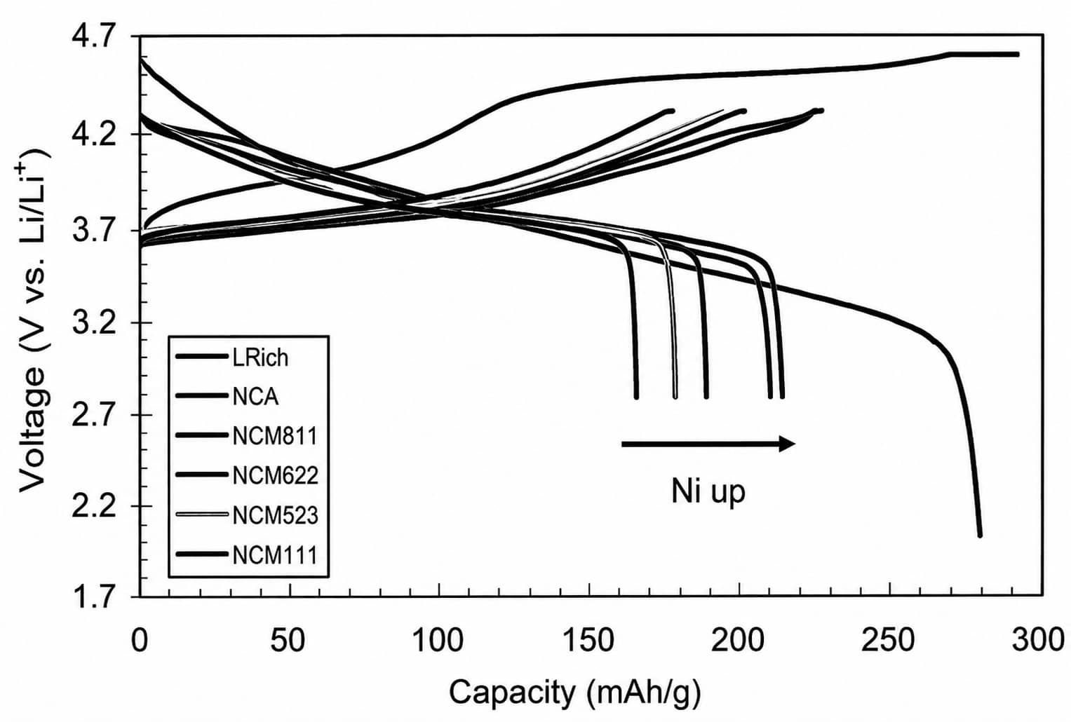
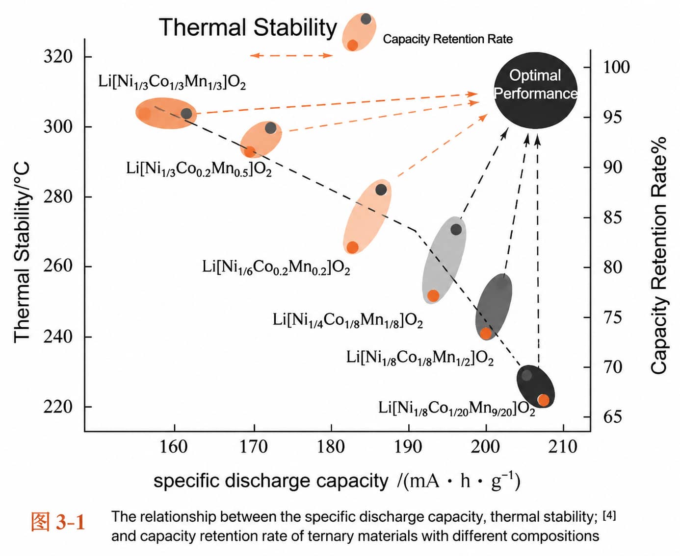
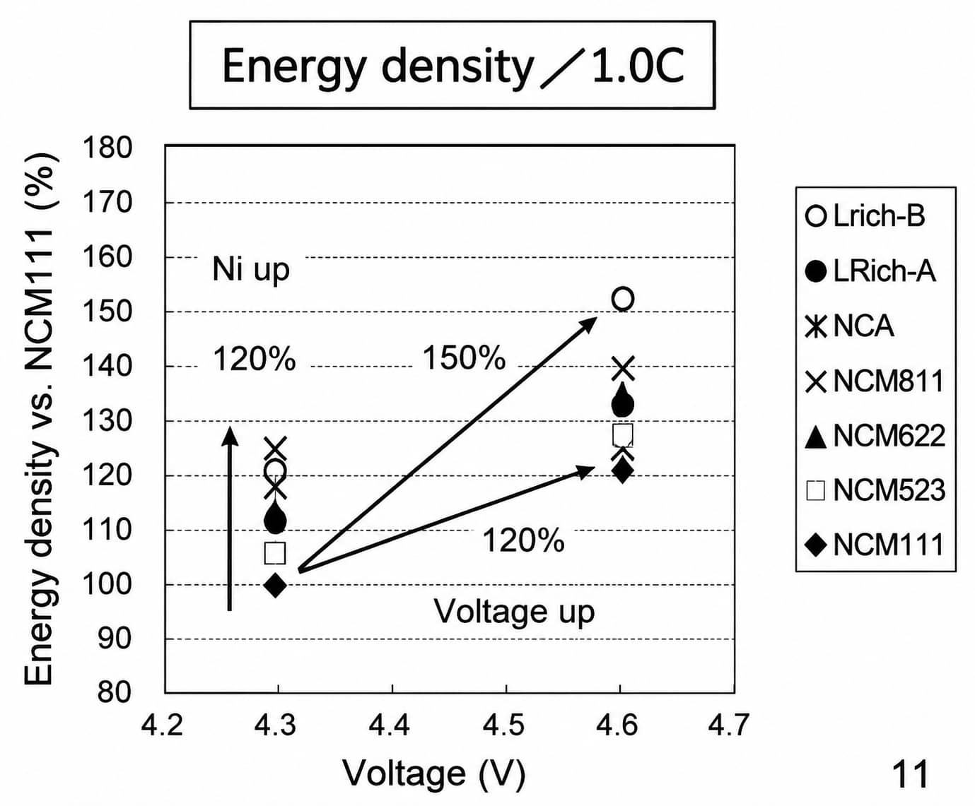
8.1 High-Nickel Low-Cobalt NCM/NCA Ternary
8.2 Cobalt-Free Layered Ni-Mn Binary Oxides (LiNi₀.₅Mn₀.₅O₂)
8.3 5V High-Voltage LNMO Spinel
8.4 Advanced Li-Rich Mn-Based Solid Solution
9. FAQ for Cathode R&D & Process Engineers
Q1: What is the biggest difference between NCM and NCA ternary cathodes?
Q2: Why can’t LFP reach the same energy density as high-nickel NCM?
Q3: How do I distinguish material intrinsic capacity loss from slurry processing defects?
Q4: What’s the primary challenge of scaling Li-rich manganese cathodes?
Q5: How to mitigate thermal stability decline in high-nickel NCM?
10. Conclusion
There is no universal “best” cathode material for lithium-ion batteries. LFP, NCM, NCA, LCO, LNMO and Li-rich cathodes each offer different trade-offs in energy density, safety, cycle life, cost and manufacturing compatibility.
Successful cathode development requires evaluation beyond powder performance, connecting material selection with slurry processing, electrode fabrication, full-cell testing and prototype validation.
Future cathode innovation will focus on high-nickel low-cobalt materials, cobalt-free systems, high-voltage cathodes and Li-rich materials, while balancing performance improvements with stability and scalable production.
Related Products & Services
Use Canrd products and R&D services to turn battery knowledge into practical experiments.
Coin Cell Case
ProductCoin cell cases for validating materials and electrochemical concepts from the article.
Use coin cell cases in your next test →Sodium Electrolyte
CategoryElectrolytes for sodium-ion battery research, compatibility tests, and cell validation.
Shop sodium electrolyte for validation →Cell Fabrication
ServiceGet support building dry cells, assembled cells, or custom formats for R&D validation.
Request cell fabrication support →Experimental Materials
CategoryBrowse materials for follow-up experiments, benchmarking, and product development.
Browse experimental battery materials →