

 contact@canrd.com

 +86 18928276992
Lithium-Ion Battery Electrolyte Wetting: Causes & How to Improve It
Electrolyte wetting is a core manufacturing step in lithium-ion battery production. It describes the process of electrolyte penetrating into porous anode, cathode and separator to form continuous lithium-ion transport channels. Poor electrolyte wetting can reduce active-material utilization, increase ionic transport resistance and polarization, and under unfavorable operating conditions may contribute to nonuniform aging, gas generation or lithium plating.
This practical guide targets battery R&D engineers and production technicians. It covers wetting fundamentals, root causes of incomplete saturation, multi-dimensional optimization strategies, quality verification and troubleshooting, following the same article structure as our battery slurry mixing guide.
Why Electrolyte Wetting Is Critical for Lithium-Ion Cells
Incomplete or non-uniform electrolyte wetting creates localized ionic conductivity differences inside the cell. Common negative impacts include:
- Reduced usable capacity, especially under high-rate discharge
- Increased interfacial resistance and voltage polarization
- Uneven current distribution and higher risk of lithium plating under specific operating conditions
- Poor batch consistency and accelerated cell degradation
Wetting challenges become much more obvious for thick high-areal-loading electrodes, high-compaction electrodes and large-format pouch, prismatic or cylindrical cells. Improving wetting requires systematic tuning of electrode structure, electrolyte formulation, separator selection and injection & soaking processes.
1. What Is Electrolyte Wetting?
Electrolyte wetting has two core dimensions:
- Surface wettability: How easily electrolyte spreads on solid material surfaces, measured by contact angle.
- Electrolyte infiltration: How electrolyte flows through the internal connected pore network of electrodes and separators. It depends on pore size, pore tortuosity, trapped gas and electrolyte physical properties.
The driving force of infiltration comes from capillary pressure, defined by:
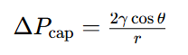
γ = electrolyte surface tension;θ = contact angle;r = effective capillary radius.
Key takeaway: Good surface wettability does not guarantee fast full infiltration. Dense, poorly connected pores can still slow down electrolyte saturation.
Neutron Imaging Visual Proof
Neutron radiography can directly observe electrolyte infiltration inside pouch cells, as shown in the images.
- At 2 min soaking: Under reduced-pressure (100 mbar) conditions, electrolyte starts penetrating the electrode assembly; under near-atmospheric pressure (960 mbar), most electrolyte remains outside the electrode assembly.
- At 15 min soaking: Under reduced pressure, electrolyte achieves a much larger wetted area.
- At 47 min soaking: The reduced-pressure group achieves nearly full wetting, while the near-atmospheric-pressure group still has large unwetted zones in the cell core.
Under the reduced-pressure condition, electrolyte penetrated the electrode assembly more rapidly than under near-atmospheric pressure in this specific experiment. In industrial electrolyte filling, evacuation and controlled pressure recovery are commonly used to reduce trapped gas and promote liquid infiltration.
2. Optimize Electrode Structure for Better Infiltration
Electrode design defines the electrolyte penetration path and pore network.
2.1 Balance areal loading and electrode thickness
Higher areal loading creates thicker electrodes and longer infiltration paths. Reducing coating loading helps wetting but sacrifices energy density. Recommended practice: Optimize pore connectivity while maintaining target loading instead of simply thinning electrodes.
2.2 Tune calendering density and porosity
Calendering improves electronic contact and volumetric energy density. Overly high compaction shrinks pore throats, raises tortuosity and raises resistance to electrolyte flow. You need to balance energy density, electronic conductivity and wettability. Validate via porosity test, pore size distribution, electrolyte uptake and EIS.
2.3 Optimize slurry dispersion and particle grading
Conductive-carbon agglomeration and nonuniform particle packing can create heterogeneous pore structures and locally reduce pore accessibility.
Particle-size distribution can be engineered to balance packing density and pore connectivity. Introducing finer particles does not automatically improve electrolyte infiltration and must be validated for each electrode formulation. The target is a well-connected pore network for both ion transport and electrolyte infiltration, not maximum porosity.
2.4 Select suitable binders
Binder type changes electrode surface energy and pore structure.
- PVDF for cathode; CMC/SBR for water-based anodes have different electrolyte affinity.
- Excess binder or binder migration during drying will alter pore accessibility. Always evaluate binder adhesion, swelling behavior and electrochemical stability.
3. Optimize Electrolyte Formulation to Lower Wetting Resistance
3.1 Adjust electrolyte viscosity
Low-viscosity solvents (EMC, DEC, DMC) reduce flow resistance. Cyclic carbonates such as EC and PC provide high dielectric properties and strong salt-solvation capability, but their interfacial compatibility differs by electrode chemistry. EC is widely used to support SEI formation on graphite, whereas PC requires careful formulation because it can be incompatible with conventional graphite anodes under some conditions.
Important: Do not blindly minimize viscosity. Solvent ratio changes will alter ionic conductivity, low-temperature performance and gas generation.
3.2 Control surface tension and contact angle
Surface tension and contact angle work together to decide capillary force. Only testing surface tension cannot reflect real wetting performance. Always measure contact angle on actual electrode samples.
3.3 Use wetting additives cautiously
Specialized electrolyte additives may modify interfacial wetting or electrolyte physical properties, but conventional surfactants should not be treated as universal battery additives. Any candidate must be validated for electrochemical stability, SEI/CEI compatibility, gas generation and cycle life.
3.4 Optimize lithium salt concentration
Salt concentration changes electrolyte viscosity and solvation structure. Tune salt concentration for the whole electrolyte system, not only for wetting improvement.
4. Optimize Electrolyte Filling & Soaking Process (Factory Priority)
Process optimization delivers fast, low-cost wetting improvement for mass manufacturing.
4.1 Precise electrolyte dosing
Sufficient electrolyte volume is the foundation of full saturation. Excess electrolyte increases inactive mass and free-liquid inventory and may complicate sealing and gas/liquid management; it cannot compensate for poor pore accessibility. Define electrolyte weight based on pore volume calculation and batch validation.
4.2 Optimize vacuum pressure profile
Vacuum filling is a complete process sequence: pre-evacuation → electrolyte injection → pressure adjustment → soaking. Key control parameters:
- Evacuation pressure & duration: Remove trapped gas, avoid electrolyte volatilization
- Injection speed: Prevent splashing and local liquid accumulation
- Pressure recovery cycles: Enhance infiltration without sacrificing throughput
No universal vacuum setting fits all cell formats. Validate pressure profiles for pouch, prismatic and cylindrical cells separately.
4.3 Moderate-Temperature Soaking (System-Specific)
Moderate heating can reduce electrolyte viscosity and accelerate infiltration, but the temperature and holding time must be validated for the specific electrolyte and cell design.
Distinguish thermal soaking (post-injection) from vacuum baking (pre-injection for moisture removal).
4.4 Set proper pre-formation resting time
Electrolyte keeps redistributing into pores during resting before formation. Insufficient resting causes uneven reaction in formation. Too long resting increases production lead time. Confirm resting time via wetting tests and formation data.
4.5 Improve injection layout
Electrolyte injection position, flow channels and electrode assembly geometry influence how quickly electrolyte reaches different regions. Pressure-assisted soaking can be tested, but excessive compression can reduce pore volume and permeability and may deform the electrode/separator stack, potentially slowing electrolyte infiltration.
5. Separator Selection Affects Overall Wetting
Separator porosity, pore size and surface wettability are part of the ion transport network.
- Ceramic-coated separators improve thermal stability; coating composition also changes electrolyte uptake.
- Adhesive separators mainly boost stacking adhesion; their wetting performance needs independent testing.
Choose separators compatible with your full electrode-electrolyte system instead of picking samples with maximum absorption only.
6. How to Test & Validate Wetting Quality
| Test Method | Purpose | Limitation |
|---|---|---|
| Electrolyte uptake & contact angle test | Material screening of electrodes/separators | Cannot replicate internal cell constraints |
| Neutron radiography | Visualize real-time electrolyte distribution | High cost, lab-scale only |
| EIS, DCIR, first-cycle CE | Indirect electrochemical evidence | Influenced by multiple cell factors |
| Post-mortem cell dissection | Check local unwetted regions | Disassembly disrupts the original electrolyte distribution. |
Best practice: Combine physical measurement, imaging and electrochemical testing to confirm uniform saturation.
7. Troubleshooting Guide for Wetting Defects
| Observed Problem | Likely Root Cause | Recommended Checks |
|---|---|---|
| Slow electrolyte infiltration | High viscosity, dense electrode, disconnected pores | Porosity, electrolyte viscosity, uptake test |
| Unwetted cell core | Long infiltration path, trapped gas | Time-resolved imaging, vacuum profile DOE |
| Batch-to-batch wetting variation | Electrode density drift, inconsistent filling weight | SPC data, electrode QC, filling weight |
| High initial impedance | Incomplete wetting or interface defects | EIS controlled soaking comparison |
8. Standard Optimization Workflow
Step 1: Build baseline record all material specs and process parameters.
Step 2: Find the limiting factor: trapped gas / slow infiltration / uneven distribution.
Step 3: Optimize process parameters first (vacuum profile, resting time, thermal soaking).
Step 4: Adjust materials if process tuning fails: electrode porosity, binder, electrolyte, separator.
Step 5: Validate electrochemical performance and batch repeatability.
9. Common Mistakes in Wetting Optimization
- Higher vacuum = better wetting: Excessive vacuum may trigger electrolyte volatilization and foaming.
- Lower viscosity guarantees better cell performance: Solvent changes impact SEI and cycle stability.
- More electrolyte means full saturation: Extra liquid cannot bypass blocked pores.
- Higher soaking temperature is always better: Overheating causes side reactions.
- Low contact angle = full internal wetting: Surface affinity and pore infiltration are separate properties.
- Low impedance confirms complete wetting: Impedance changes come from many factors.
FAQ
Q1: What causes poor electrolyte wetting?
A: Main causes include over-compacted electrodes, thick coatings, disconnected pore networks, high electrolyte viscosity, trapped gas, insufficient resting time and restrictive cell geometry.
Q2: How does vacuum filling improve wetting?
A: Vacuum removes trapped air inside the electrode and separator pores. Pressure difference plus capillary force drives electrolyte into pore networks. The effect depends on the full vacuum cycle and cell structure.
Q3: Does higher porosity always improve wetting?
A: No. Infiltration also depends on pore connectivity, pore size and tortuosity. High porosity with isolated pores still wets slowly.
Q4: Can heating speed up electrolyte soaking?
A: Moderate heating reduces viscosity and accelerates infiltration. Temperature and duration need validation to avoid side reactions.
Q5: How to confirm fully wetted cells?
A: Use a combination of physical infiltration tests, imaging tools and electrochemical characterization. No single electrochemical test can independently prove full saturation.
Conclusion
Electrolyte wetting is a coupled challenge of materials and manufacturing processes. Vacuum filling and soaking process tuning are the preferred starting point for existing cell chemistries. If process optimization is insufficient, systematically optimize electrode pore architecture, binder formulation, electrolyte composition and separator selection. The target is not only faster electrolyte absorption, but uniform, repeatable saturation to support stable formation, low polarization and consistent battery mass production.
منتجات وخدمات ذات صلة
استخدم منتجات Canrd وخدمات البحث والتطوير لتحويل معرفة البطاريات إلى تجارب عملية.
علبة coin cell
منتجعلب coin cell للتحقق من المواد والمفاهيم الكهروكيميائية المذكورة في المقالة.
استخدم علب coin cell في اختبارك التالي →إلكتروليت الصوديوم
فئةإلكتروليتات لأبحاث بطاريات الصوديوم-أيون واختبارات التوافق والتحقق من الخلايا.
تصفح إلكتروليت الصوديوم للتحقق →تصنيع الخلايا
خدمةاحصل على دعم لبناء خلايا جافة أو مجمعة أو صيغ مخصصة للتحقق في البحث والتطوير.
اطلب دعم تصنيع الخلايا →مواد تجريبية
فئةتصفح مواد للتجارب اللاحقة والمقارنة وتطوير المنتجات.
تصفح مواد البطاريات التجريبية →
