
Battery Binder Guide: PVDF vs CMC/SBR — Which to Choose for Cathode and Anode Electrodes?
Introduction
Lithium-ion battery binders may account for only a small fraction of the electrode, but they strongly influence slurry stability, coating quality, adhesion, and long-term electrode integrity. Choosing the right binder therefore requires more than comparing PVDF, CMC, or SBR by name.
This guide explains how to select and validate binders for NCM, LFP, graphite, and silicon-carbon electrodes, while addressing practical issues such as CMC viscosity variation, PVDF discoloration, high-nickel slurry gelation, and electrode peeling.
1. What Core Roles Do Binders Play In Lithium Electrodes?
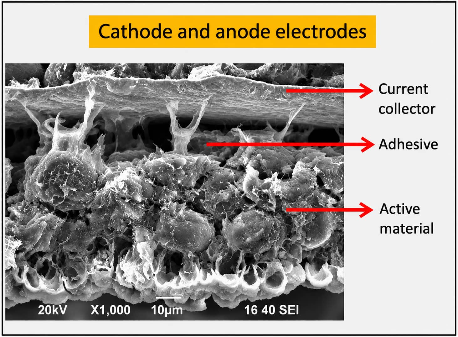
1.1 Slurry Rheology & Stabilization Functions
- Provide proper viscosity to prevent solid particle sedimentation and long-term stratification during storage
- Improve powder wettability to eliminate hard agglomerates during planetary kneading
- Optimize fluidity to support uniform roll-to-roll continuous coating
1.2 Electrode Structural Protection Functions
- Bond active material, conductive carbon and metal current collectors into a complete conductive network
- Maintain coating integrity under calendaring pressure without surface cracking or fragmentation
- Preserve inter-particle conductive contact after thousands of charge-discharge cycles with mild material volume
Reference Ideal Binder Performance Benchmarks
- Good adhesion to aluminum/copper foil, no peeling after long-term electrolyte soaking
- Stable electrochemical window matching the cell’s working voltage range without side reactions
- High melting point and low swelling rate; excessive swelling breaks inter-particle conductive contact
2. Classification & Brand Matrix Of Commercial & Experimental Battery Binders
2.1 Mainstream Mass-Production Binders (PVDF / CMC / SBR / PTFE)
PVDF (Polyvinylidene Fluoride)
- Solvent trait: Only soluble in NMP organic solvent, incompatible with pure water-based slurry systems
- Advantages: Excellent chemical inertness with carbonate electrolyte, stable anti-oxidation performance under high cathode cut-off voltage
- Limitation: Higher raw material cost vs aqueous CMC/SBR systems
CMC + SBR Composite Aqueous Anode System
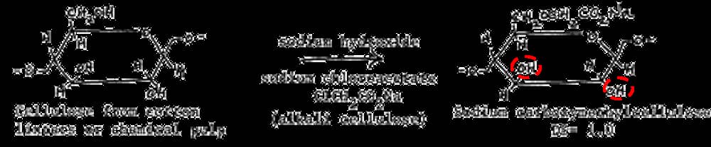
- Processing merit: Zero toxic NMP waste, lower overall production raw material cost
- Limitation: Cannot resist high oxidation potential of ternary/LCO cathodes, not applicable for positive electrode production
PTFE
2.2 Complete Manufacturer & Product Grade Reference Table
2.3 Emerging Experimental Binders (PAA, PAN, PMMA, PAI, PI, PVA, Sodium Alginate)
- PAA (Polyacrylic Acid): High mechanical constraint force for high-expansion silicon-carbon anodes
- PAN: Optimizes electrode low-temperature discharge and rate performance
- PMMA / PAI / PI: Experimental high-voltage resistant fluorine-free polymers
- PVA / Sodium Alginate: Low-cost water-based green anode binders
Detailed industrialization obstacles of PAA/PI can be found in Section 8 and supplementary mechanism analysis in Binder Part II.
3. How To Match The Correct Binder For Each Electrode Material
| Electrode Material | Recommended Binder System | Core Matching Reason |
|---|---|---|
| LCO Low-Voltage Cathode | Conventional PVDF Homopolymer | Stable anti-oxidation performance under 4.2–4.35V |
| NCM523 / NCM622 Mid-Nickel Ternary | Standard PVDF Copolymer | Balanced viscosity and slurry stability |
| NCM811 / NCA High-Nickel Ternary | Anti-Gel Modified PVDF | Suppress gelation triggered by high surface alkalinity |
| LFP Iron Phosphate Cathode | Low-Viscosity Modified PVDF | Improve fluidity for high solid loading slurry |
| Graphite Anode (Mass Production) | CMC + SBR Water-Based System | Flexible bonding to mild graphite volume expansion |
| Silicon-Carbon Composite Anode | Lithiated PAA | Strong mechanical restraint for ~300% Si expansion |
| LTO Lithium Titanate Anode | PVDF + NMP Solvent | Stable low-potential anode matching |
| Supercapacitor Electrodes | PTFE Fluoropolymer | Ultra-wide chemical corrosion resistance |
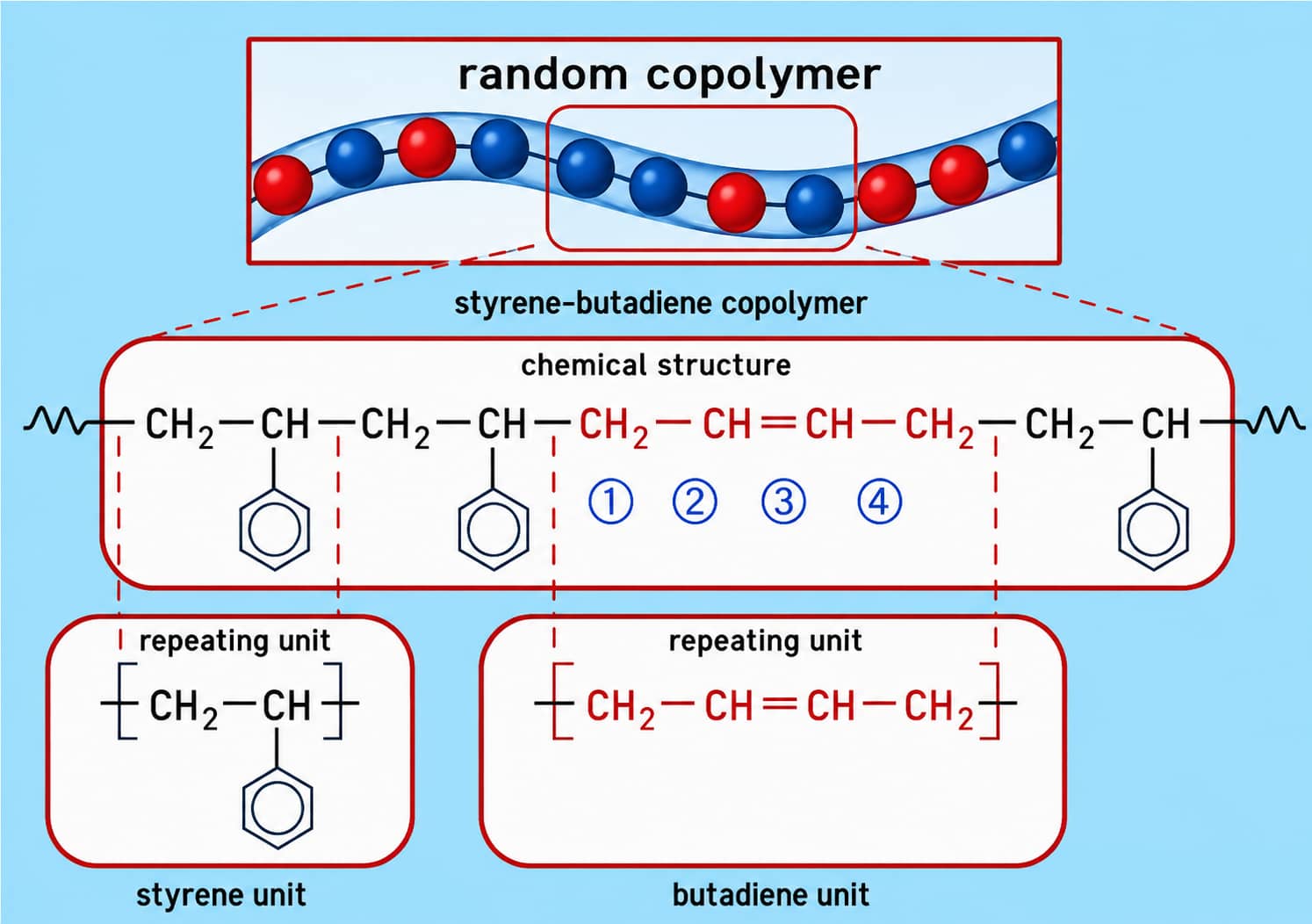
4. CMC vs SBR: Separate Functional Roles In Aqueous Anode Slurries
| Material | Primary Function | Secondary Auxiliary Function |
|---|---|---|
| CMC | Adjust slurry viscosity & prevent solid sedimentation | Weak auxiliary adhesive force |
| SBR | Provide most electrode peeling adhesion | Increase coating flexibility to avoid calendaring cracks |
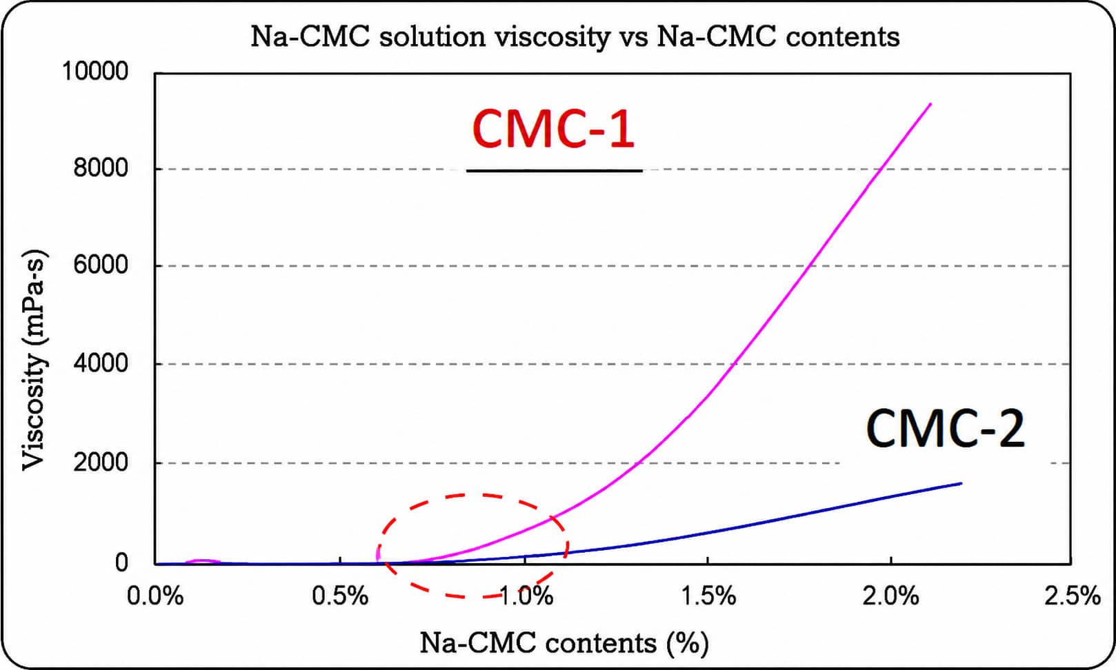
5. Why Equal CMC Loading Creates Different Slurry Viscosity
- CMC molecular weight distribution (higher MW = higher viscosity at equal loading)
- Carboxymethyl group substitution degree on cellulose chains
- Raw material production process differences between suppliers
Production reminder: Switching CMC suppliers or grades requires small-batch slurry pre-trials to adjust mixing parameters before mass batching.
6. Critical Binder Performance Metrics & Standard Lab Testing Methods
| No. | Performance Parameter | Practical Production Impact |
|---|---|---|
| 1 | Molecular Weight | Determines electrode adhesion and solvent solubility |
| 2 | Viscosity | Controls slurry fluidity & long-term suspension stability |
| 3 | Impurity Content | Excess impurities cause cell self-discharge |
| 4 | Solid Content | Basis for accurate formula feeding calculation |
| 5 | PH Value | Extreme pH triggers slurry agglomeration / gelation |
| 6 | Tg Glass Transition Temp | Low Tg = flexible coating; high Tg = brittle & easy to crack |
| 7 | Adhesion Strength | Direct index to judge powder shedding risk |
| 8 | Solubility | Decides matching solvent (NMP / water) |
| 9 | Electrochemical Stability Window | Limits matching cathode cut-off voltage |
| 10 | Ionic Conductivity | Affects cell DCIR & fast-charging performance |
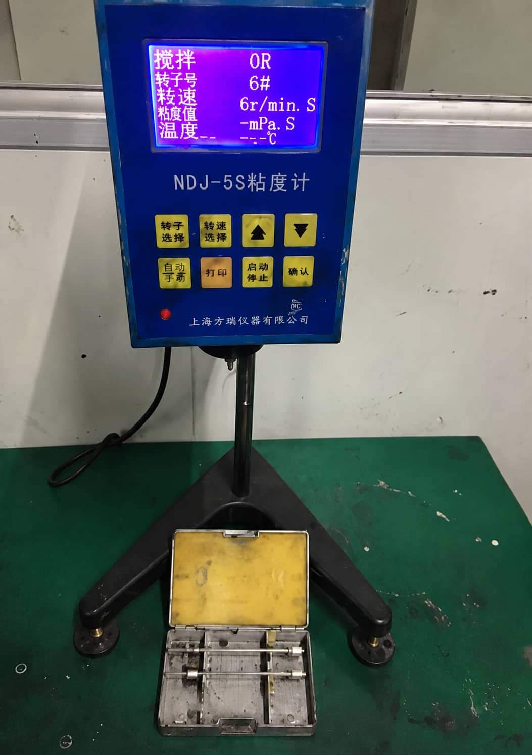
6.1 Slurry Viscosity & Rheology Test
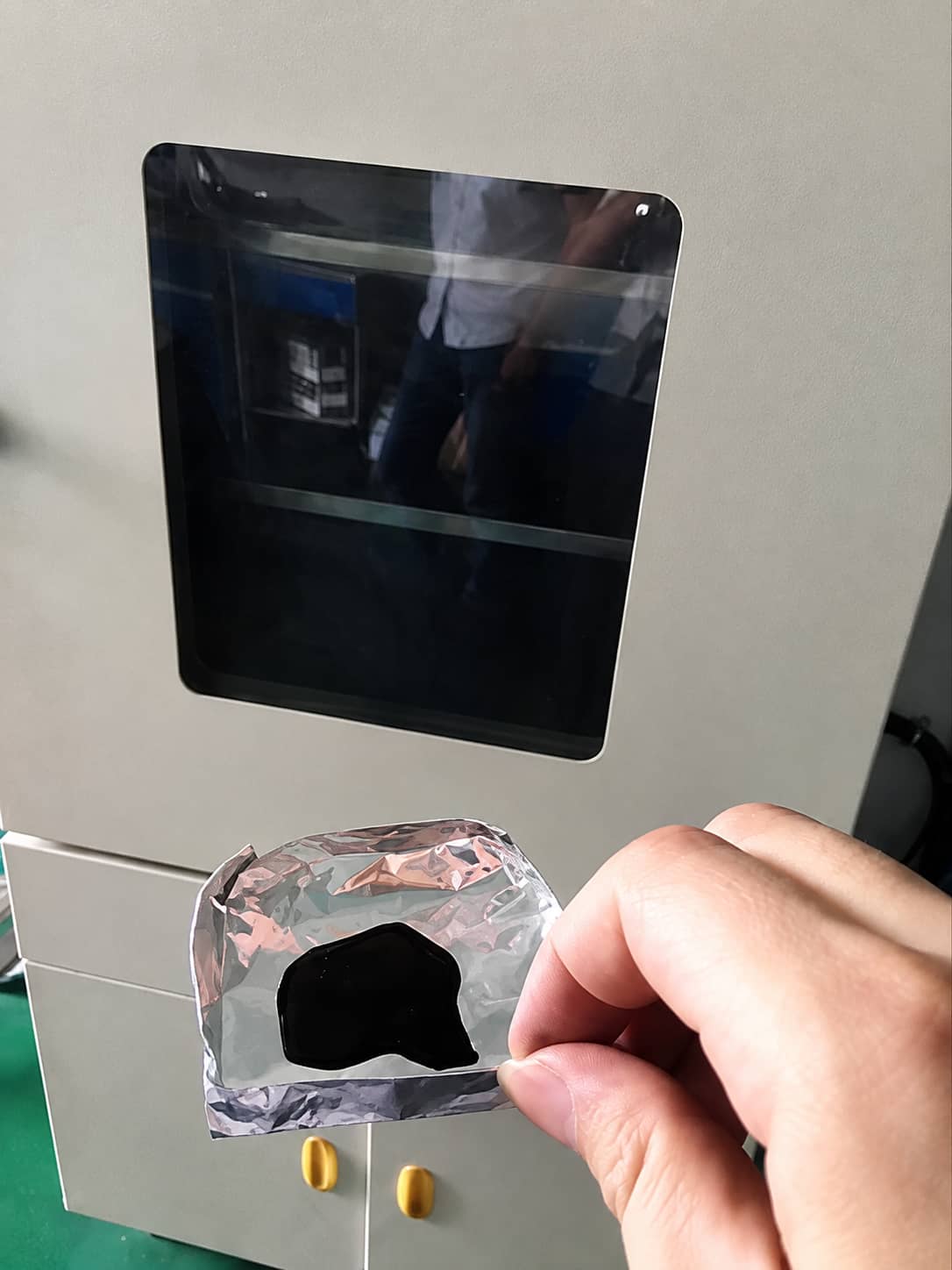
6.2 Solid Content Measurement
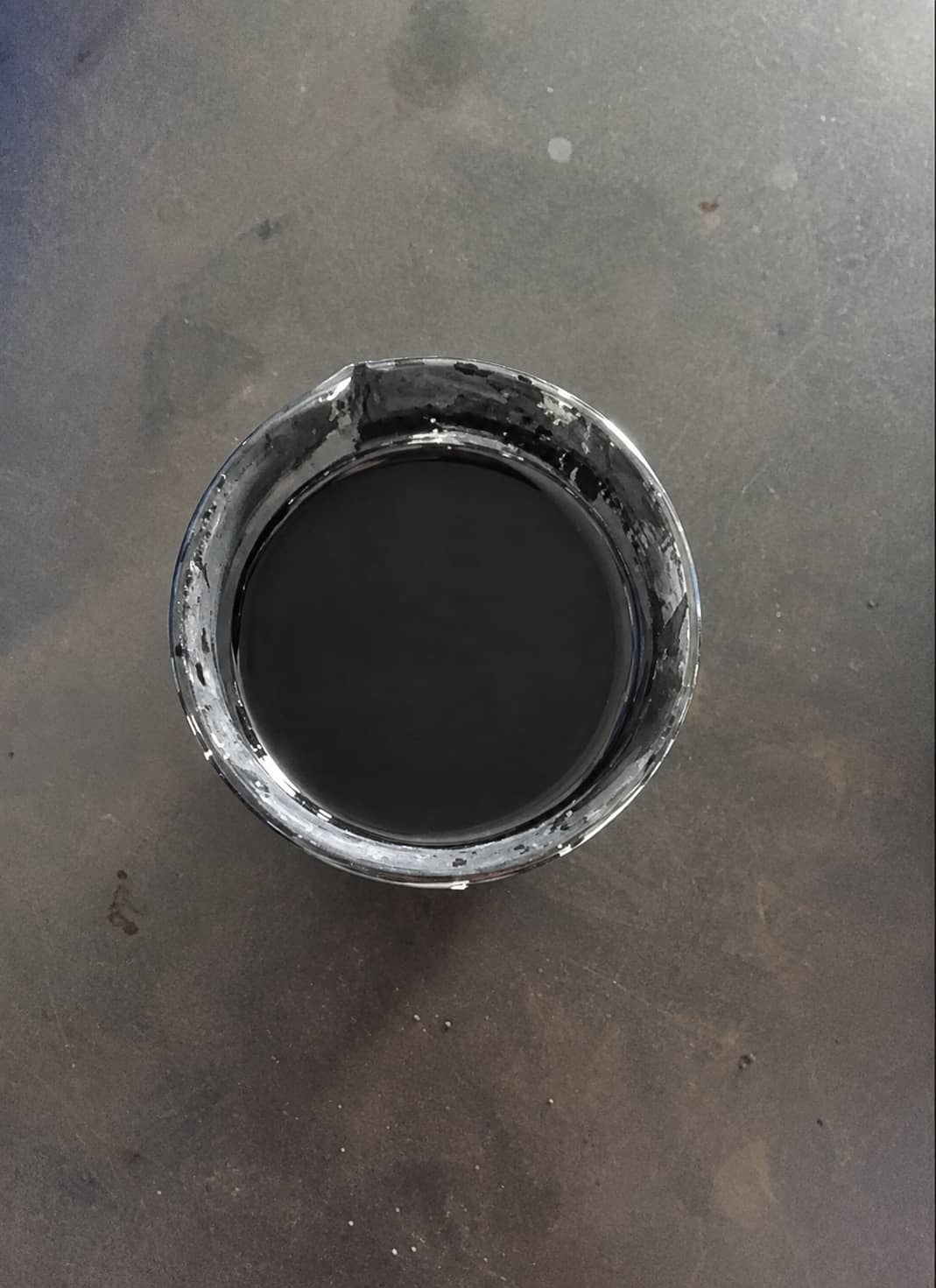
6.3 Slurry Static Stability Test
6.4 Electrode Adhesion Peel Test
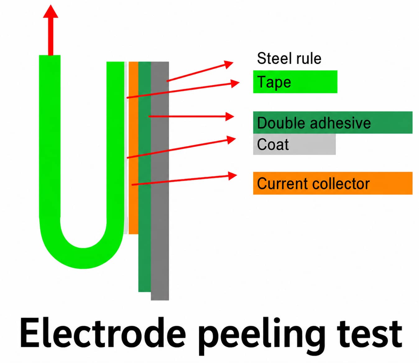
Advanced Electrolyte Swelling Validation
7. Common Production Defects Rooted In Binder Abnormality
7.1 PVDF NMP Solution Discoloration: Mechanism & Usability Judgment
7.2 High-Nickel Cathode Slurry Gelation: Three Core Triggers & Fixes
- High residual alkali on NCM811/NCA cathode surface
- Conventional PVDF susceptible to alkali-induced cross-linking
- Excess ambient moisture in mixing workshop
Optimization schemes: Adopt anti-gel modified PVDF; control workshop RH below reference 10%; pre-wash cathode powder to reduce surface alkalinity.
7.3 Electrode Peeling / Powder Shedding: Distinguish Binder vs Process Causes
| Observed Defect | Binder-Related Causes | Other Process Inspection Priorities |
|---|---|---|
| Full coating detaches from foil | Insufficient binder dosage; low-molecular PVDF/CMC | Dirty current collector; over-calendering pressure |
| Local spot powder shedding | Uneven binder dispersion during mixing | Excessive coating loading; severe drying shrinkage |
| Post-rolling micro-cracks | Lack of flexible SBR/PAA component | Too fast oven heating; over-dried coating |
8. Industrialization Barriers Of New Silicon-Anode Binders (PAA / PI)
Lithiated PAA Drawbacks
PI Polyimide Limitations
- Requires 250℃ high-temperature post-curing, raising energy cost
- High rigidity leads to easy cracking after electrode deformation
- Consumes lithium ions at initial cycle, low first-cycle coulombic efficiency
- Expensive raw material
Full supplementary new binder test data: Binder Part II
9. Complete New Binder Validation Workflow: Slurry → Half-Cell → Full-Cell
- Single-component binder physical index testing (viscosity, solid content, pH)
- Small-batch slurry preparation & static stability observation
- Pilot coating + calendaring + peel adhesion test
- Coin half-cell cycle & swelling aging screening
- Small pouch full-cell verification (high-temp storage, low-temperature discharge, impedance)
- Pilot batch repeatability trial before formal mass production switch
10. Future R&D Directions For Battery Adhesive Materials
- Functional molecular modification: Integrate anti-swelling, anti-de-HF functional groups into PVDF polymer chains
- Low-cost water-based cathode binder: Develop water-soluble binders to eliminate expensive toxic NMP solvent
- High-elastic polymer design for silicon electrodes: Optimize flexibility to adapt large silicon volume expansion
11. FAQ For R&D & Production Line Engineers
Q1 What is the core difference between PVDF and CMC/SBR binder systems?
Q2 My NCM811 cathode slurry gels during mixing, how to solve this issue?
Q3 PVDF glue turns amber after storage, must I discard the whole batch?
Q4 What binder is recommended for silicon-carbon composite anodes?
Q5 Electrode peels after calendaring, should I immediately increase binder dosage?
Q6 Identical CMC dosage creates different slurry viscosity, what causes this?
12. Conclusion
Related Products & Services
Use Canrd products and R&D services to turn battery knowledge into practical experiments.
Coin Cell Case
ProductCoin cell cases for validating materials and electrochemical concepts from the article.
Use coin cell cases in your next test →Sodium Electrolyte
CategoryElectrolytes for sodium-ion battery research, compatibility tests, and cell validation.
Shop sodium electrolyte for validation →Cell Fabrication
ServiceGet support building dry cells, assembled cells, or custom formats for R&D validation.
Request cell fabrication support →Experimental Materials
CategoryBrowse materials for follow-up experiments, benchmarking, and product development.
Browse experimental battery materials →