

 contact@canrd.com
 +86 18928276992


Details
| Canrd | 10*10cm | 5 sheets/pack | Coating | ||||
| NO. | Electrode Name | Model | Main Material | Active Material Capacity (mAh/g) | Loading | Areal Density (mg/cm²) | Areal Capacity (mAh/cm²) |
| 1 | NCA Electrode | SY51 | NCA-S (Nickel Cobalt Aluminum Oxide) | 195 | 94.50% | 17.66 | 3.25 |
| 2 | Ni90 Electrode | SY41 | Ni90 Single Crystal NCM | 195 | 94.50% | 9.50 | 1.75 |
| 3 | NCM811 Electrode | SY33 | NCM811 Single Crystal | 188 | 94.50% | 9.20 | 1.63 |
| 4 | NCM811 Electrode | SY34 | — | 188 | 94.50% | 21.50 | 3.82 |
| 5 | NCM622 Electrode | SY25 | NCM622 Single Crystal-B | 168 | 96.70% | 10.00 | 1.62 |
| 6 | NCM622 Electrode | SY24 | — | 168 | 96.70% | 21.60 | 3.51 |
| 7 | NCM523 Electrode | SY15 | NCM523 | 165 | 94.00% | 19.70 | 3.06 |
| 8 | NCM523 Electrode | SY13 | NCM523 | 165 | 94.00% | 10.50 | 1.63 |
| 9 | LCO Electrode | LC02 | High Voltage Lithium Cobalt Oxide-Z-4.45V | 178 | 96.40% | 10.00 | 1.72 |
| 10 | LRM Electrode | FL01 | Lithium-rich Manganese-based-E | 280 | 95.00% | 5.96 | 1.59 |
| 11 | Graphite Electrode | SM02 | Natural Graphite (Standard)-A | 340 | 95.70% | 5.80 | 1.89 |
| 12 | Fast Charging Graphite Electrode | SM04 | Fast Charging Graphite-B | 350 | 96.70% | 5.60 | 1.90 |
| 13 | Silicon Carbon Electrode | SC02 | Silicon Carbon Anode 1800 (Porous Carbon Deposited Silicon) | 420 | 95.00% | 4.80 | 1.92 |
| 14 | NFM Electrode | NT02 | Sodium Nickel Iron Manganese Oxide | 127 | 95.50% | 12.27 | 1.49 |
| 15 | NFM Electrode | NT03 | — | 127 | 95.50% | 8.00 | 0.97 |
| 16 | Hard Carbon Electrode | YT02 | Imported Hard Carbon (5 μm) | 300 | 95.50% | 6.00 | 1.72 |
| 17 | LFP Electrode | LF07 | Lithium Iron Phosphate (High Compaction Density) |
150 | 91.50% | 12.30 | 1.69 |
| 18 | LNMO Electrode | NM01 | High Voltage Lithium Nickel Manganese Oxide-B | 130 | 96.00% | 7.50 | 2.00 |
| 19 | NFPP Electrode | NF01 | Sodium Iron Phosphate Pyrophosphate | 100 | 93.50% | 15.30 | 1.43 |
| 20 | Vanadium Pentoxide Electrode | VO02 | Vanadium Pentoxide | 300 | 80.00% | 5.00 | 1.20 |
| 21 | Manganese Dioxide Electrode | MO01 | Manganese-based or Vanadium-based Material | 100 | 80.00% | 5.00 | / |
| 22 | Zinc Negative Electrode | ZA01 | Pure Zinc Powder / Alloy Zinc Powder | / | 70.0%–96.0% | 5.0–15.0 | / |
MOQ for Custom Small Electrode Sheets: 10*10cm/pcs,5cs/pack,1pack
To place an order or request a quotation, please Contact Us.
1. Store under vacuum or in a glove box using two layers of sealed bags, especially for high-nickel or sodium-ion cathode materials. Improper storage may lead to increased internal resistance of the battery.
2. Electrode sheets are not roll-pressed; they need to be roll-pressed according to the recommended pressing density.
3. The coating area density should be determined based on actual weighing results, and it does not include the current collector.
4. Actual active material mass (mg) = (weight of the small disc in mg – current collector area density in mg/cm² × area of the small disc in cm²) × active material ratio.
5. Theoretical active material amount (mg) = coating area density in mg/cm² × active material ratio × area of the small disc in cm².
6. Theoretical areal capacity (mAh/cm²) = coating area density in mg/cm² × active material ratio × gravimetric capacity in mAh/g ÷ 1000.
7. When calculating gravimetric capacity, use the actual weighed amount of active material since the coating area density may have tolerances; the actual weighing takes precedence.
8. Creases: single-sided electrode sheets tend to curl after roll-pressing; flattening and packaging may cause creases.
This product must be tested in accordance with the test methods and electrolytes recommended by Coulter to achieve the corresponding performance.
Since the test method and electrolyte have a great influence on the performance of the battery, any change in the test method or electrolyte may reduce the performance of the pole piece; be sure to check this information before purchasing.
| Item | Specification |
| Areal Capacity (mAh/cm²) | 1.73 |
| Current Collector Areal Density (mg/cm²) | 3.3 |
| Current Collector Thickness (µm) | 12 (Al foil) |
| Electrode Sheet Size | 10 × 10 cm |
| Active Material Ratio (%) | 95.50% |
| Compatible Full-Cell Electrode Model (N/P Ratio) | NT02XX (1.16) |
| Compacted Density (g/cc) | 0.90 (Uncalendered electrode, compaction value not provided) |
| Active Material | Imported Hard Carbon (5 µm) |
| Shelf Life | 6 months (vacuum sealed); use within 1 month after opening |
| Recommended Electrolyte | KLD-NC06 |
| Electrode Name | Sodium-Ion Hard Carbon Electrode Sheet |
| Electrode Code | YT02XX |
| Specific Capacity (mAh/g) | 300 (0.00–2.00 V) |
| Test Conditions | 25°C, 0.20→0.15→0.12→0.10→0.08→0.06→0.05→0.04→0.03→0.02→0.015→0.012→0.01C / 0.02mA / 0.01mA discharge to 0.00V; then 0.1C charge to 2.00V |
| Usage Recommendation | Calender before punching & drying; Dry at 85–105°C for 4h (vacuum drying requires 2 gas exchanges); Active mass based on actual disc weighing |
| Coating Areal Density (mg/cm²) | 6.00 (tolerance ±2.0%) |
Half-Cell Testing
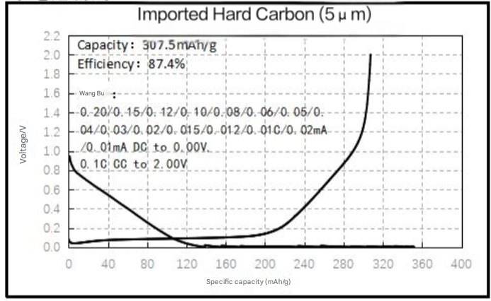
Procedure Description:
- Ambient temperature 25°C, rest for 4h
- Discharge at 0.20C rate (constant current) to 0V, discharge at 0.15C rate (constant current) to 0V,
- Discharge at 0.12C rate (constant current) to 0V, discharge at 0.10C rate (constant current) to 0V,
- Discharge at 0.08C rate (constant current) to 0V, discharge at 0.06C rate (constant current) to 0V,
- Discharge at 0.05C rate (constant current) to 0V, discharge at 0.04C rate (constant current) to 0V,
- Discharge at 0.03C rate (constant current) to 0V, discharge at 0.02C rate (constant current) to 0V,
- Discharge at 0.015C rate (constant current) to 0V, discharge at 0.012C rate (constant current) to 0V,
- Discharge at 0.01C rate (constant current) to 0V, discharge at 0.02mA rate (constant current) to 0V,
- Discharge at 0.01mA rate (constant current) to 0V, rest for 3min.
- Charge at 0.1C rate (constant current) to 2.00V, rest for 3min.
Need R&D Support?
Browse key product categories and connect battery materials with Canrd's R&D services for testing, fabrication, and project support.
Experimental Materials
CategoryCathode, anode, electrolyte, separator, and other materials for battery research.
Shop cathode, anode & electrolyte materials →Lab Equipment
CategoryBattery lab equipment for pilot lines, fixtures, and testing workflows.
Browse battery lab equipment →Electrodes & Cells
CategoryCustom electrodes, dry cells, and battery cell components for R&D validation.
View custom battery electrodes & cells →Sodium Electrolyte
CategorySodium-ion electrolyte options for sodium battery research and validation.
Shop sodium battery electrolytes →R&D Services
ServiceFull-chain battery R&D services from material evaluation to cell fabrication and failure analysis.
Explore Canrd R&D services →Material Evaluation
ServiceCharacterization, electrochemical testing, and compatibility evaluation for battery materials.
Evaluate your battery materials →Electrode Fabrication
ServiceCustom electrode sheets and rolls based on your target chemistry and process needs.
Request electrode fabrication →Cell Fabrication
ServiceDry cells, assembled cells, and custom-format cell builds for R&D validation.
Build custom research cells →Contact
PageAsk Canrd to match products, materials, and services for your project.
Get product and R&D support →