



Lithium Battery Electrode Coating Defects
canrd July 16, 2026 209
Electrode coating defects are the top source of yield loss in lithium battery mass production. Common failures including powder peeling, surface cracking, edge curling and linear scratches mostly stem from unqualified slurry status, mismatched coating equipment parameters or unreasonable oven drying gradients. If left unrectified, these tiny surface flaws will expand during calendering, slitting and winding, triggering capacity attenuation and internal short circuits in finished cells.
This article focuses exclusively on coating failures generated on industrial transfer and slot-die continuous production lines. For full coating line structure, equipment specifications and standard process parameters, see our Lithium Battery Electrode Coating Process Guide. For manual coating operations and unique faults appearing in R&D lab sample preparation, refer to our Laboratory Battery Electrode Coating Methods Article.
Where Coating Defects Occur in Battery Manufacturing
Most coating-related defects originate during three upstream core links: slurry mixing & feeding, continuous coating station, and multi-stage drying oven. Subsequent processes such as calendering and winding rarely create brand-new coating defects, but they will amplify existing structural weaknesses of coated electrodes and worsen visible abnormalities like crack expansion and large-area powder shedding.
Relationship Between Slurry Quality and Coating Defects
Slurry physical properties and mixing uniformity lay the foundation of electrode surface quality. All typical coating abnormalities have direct correlations with improper slurry preparation. The matching table below links common slurry issues to corresponding coating failures, with cross-reference to our cathode and anode slurry mixing technical guides for mixing parameter adjustment schemes.
| Slurry Abnormality | Triggered Coating Defect |
|---|---|
| Insufficient high-speed dispersion | Electrode bright spots (particle agglomeration) |
| Unremoved residual microbubbles | Coating white pinhole spots |
| Excessively high slurry viscosity | Parallel coating stripes, poor leveling |
| Uneven binder distribution & demulsification | Electrode shedding & powder peeling |
| Mixed dust, oil or hard foreign particles | Coating scratches, Marangoni crater pits |
8 Major Lithium Battery Electrode Coating Defects
All defects are sorted by hazard severity and logical reading flow: adhesion failure → mechanical deformation → surface damage → uneven coating morphology. Every case uniformly classifies root causes into three fixed categories: Slurry-related, Equipment-related, Drying-related, and attaches targeted mass-production optimization solutions.
1. Electrode Shedding and Powder Peeling
Phenomenon
Mass active material detaches from copper/aluminum foil during rewinding, calendering or peel strength testing; clear separation gaps can be observed under optical and SEM microscopes. Water-based graphite anodes with CMC/SBR binders suffer this issue far more frequently than PVDF-coated cathodes.
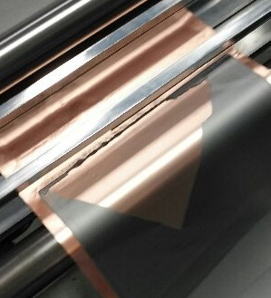

Root Cause Category Breakdown
- Slurry-related: Insufficient binder addition ratio, SBR demulsification in anode slurry
- Equipment-related: Bare foil without carbon coating, weak substrate interfacial adhesion
- Drying-related: Oven heating zone temperature rises sharply, fast solvent evaporation leads to binder precipitation
Targeted Industrial Optimization Plans
Adjust slurry mixing formula to raise reasonable binder dosage; adopt carbon-coated copper/aluminum foil for high-performance battery models; lower the initial heating temperature of drying ovens and extend slow solvent volatilization residence time.
2. Electrode Cracking
Phenomenon
Visible long or dense microcracks spread across the electrode surface after drying; cracks expand severely after roller compaction and cause massive powder loss during post-processing.
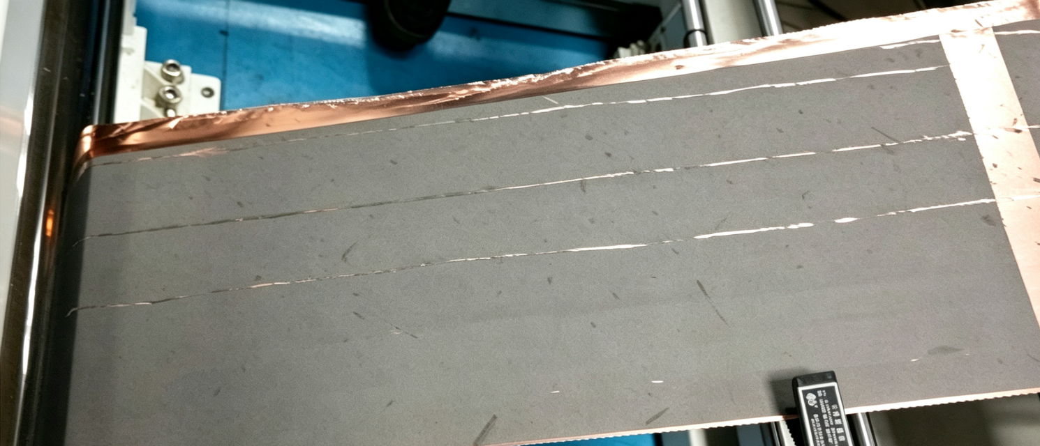
Root Cause Category Breakdown
- Slurry-related: Ultra-low slurry solid content, excessive solvent proportion
- Equipment-related: Over-thick single-side coating loading set on slot-die/transfer lines
- Drying-related: Oven constant-temperature zone airflow volume is too high, production line speed is overly fast
Targeted Industrial Optimization Plans
Properly increase slurry solid content; reduce single-side coating weight to factory standard range; cut constant zone circulating air volume and slow down overall line speed to prolong oven residence time.
3. Electrode Curling After Drying
Phenomenon
Two edges of single-side coated foil tilt upward immediately after exiting the cooling zone, resulting in foil offset, dimensional deviation and wrinkling during slitting and winding.

Root Cause Category Breakdown
- Slurry-related: High-shrinkage binder system, excessive solvent volatilization stress
- Equipment-related: Unmatched tension control between unwinding and rewinding rollers
- Drying-related: Unreasonable three-stage heating-cooling temperature gradient without stress relief
Targeted Industrial Optimization Plans
Optimize binder types to lower drying shrinkage coefficient; calibrate full-line constant tension system; redesign oven temperature curve to release coating film stress step by step.
4. Coating Scratches and Bare Foil Exposure
Phenomenon
Continuous linear blank streaks run through the full length of coated foil, completely exposing the underlying metal current collector, which cannot be repaired in subsequent working procedures.
Root Cause Category Breakdown
- Slurry-related: Unfiltered hard agglomerate particles mixed in slurry liquid
- Equipment-related: Dried slurry residue accumulated on doctor blade or slot-die lip
- Drying-related: No direct drying-induced causes
Targeted Industrial Optimization Plans
Add double-stage slurry sieving before feeding to coating transit tanks; arrange fixed daily shift intervals to clean die and blade residual dry slurry.
5. Coating White Spots and Bubble Defects
Phenomenon
Randomly distributed circular hollow pinholes on electrode surfaces after baking; no active powder exists inside each pit, easily triggering localized lithium precipitation during long battery cycling.

Root Cause Category Breakdown
- Slurry-related: Inadequate vacuum defoaming during slurry mixing, retained micro air bubbles
- Equipment-related: Unsealed slurry feeding pipeline introduces new air bubbles
- Drying-related: Fast initial oven temperature rise accelerates bubble rupture
Targeted Industrial Optimization Plans
Extend vacuum defoaming duration in the mixing procedure; fully seal all slurry transfer pipelines; set mild low-temperature preheating section in drying ovens.
6. Coating Cratering (Marangoni Effect)
Phenomenon
Circular sunken pits with raised outer edges on coating surfaces; tiny dust or oil foreign impurities can be found at the center of each pit under SEM observation, distinguishing them from clean hollow bubble pinholes.

Root Cause Category Breakdown
- Slurry-related: Unbalanced surface tension among powder, solvent and binder, mixed oil/dust contaminants
- Equipment-related: Unclean dust-free coating workshop environment
- Drying-related: Over-high initial airflow aggravates surface tension gradient
Targeted Industrial Optimization Plans
Adjust solvent and dispersant formula to balance overall slurry surface tension; upgrade workshop dust purification grade; reduce heating zone wind speed at the oven inlet.
7. Electrode Bright Spots Caused by Poor Slurry Dispersion
Phenomenon
Tiny reflective bright speckles scattered across electrode surfaces, only prominent after calendering compression; microscopic inspection reveals undispersed hard active material agglomerates inside bright spots.

Root Cause Category Breakdown
- Slurry-related: Insufficient high-speed dispersion mixing time, inadequate dispersant dosage
- Equipment-related: Slurry agitator operating speed below process standard
- Drying-related: No direct drying-induced causes
Targeted Industrial Optimization Plans
Prolong high-speed homogenization time during slurry preparation; supplement dispersant proportion according to material specifications; calibrate mixing tank agitator rotation speed regularly.
8. Coating Stripes
Phenomenon
Equidistant parallel linear textures covering the full coating width, completely copied from coating rollers or slot-die lips onto wet slurry films, leading to uneven local active material loading weight.

Root Cause Category Breakdown
- Slurry-related: Excessively high slurry viscosity, poor liquid leveling capacity
- Equipment-related: Uneven gap between slot-die lip and moving foil web
- Drying-related: Low slurry temperature entering the oven reduces fluidity
Targeted Industrial Optimization Plans
Adjust solvent additive volume to lower slurry viscosity within factory specification range; re-calibrate die-to-web clearance; properly raise pre-circulating slurry temperature before coating feeding.
Industrial vs Laboratory Coating Defect Comparison Table
This table differentiates failure occurrence frequency between mass-production continuous lines and lab manual coating platforms, clearly separating unique R&D defects from industrial mass-production abnormalities.
| Defect Type | Occurrence Frequency (Industrial Line) | Occurrence Frequency (Lab Coating) | Core Shared Root Cause |
|---|---|---|---|
| Foil Wrinkling | Low | High | Unstable substrate fixation & tension control |
| Nickel Foam Poor Infiltration | None | Very High | High-viscosity slurry incompatible with porous substrates |
| Electrode Shedding & Peeling | High | Medium | Insufficient binder interfacial adhesion |
| Bubble White Pinholes | High | Medium | Residual microbubbles inside mixed slurry |
| Electrode Cracking | High | Medium | Excessive drying shrinkage stress |
| Coating Scratches | High | Low | Hard solid particles mixed in slurry liquid |
| Marangoni Crater Pits | High | Low | Dust/oil contamination in production environment |
| Coating Stripes | High | Low | Over-high slurry viscosity & poor leveling |
ℹ️ Lab-exclusive defects including nickel foam incomplete infiltration and glass rod rolling powder shedding are fully explained with solutions in our laboratory coating technical article.
How to Prevent Electrode Coating Defects Systematically
- Slurry Front-End Control Strictly implement vacuum defoaming, double-stage filtration and full dispersion standards; adjust solid content, viscosity and binder ratio according to corresponding slurry mixing guides.
- Coating Equipment Daily Maintenance Set daily cleaning schedules for slot-die lips, doctor blades and slurry circulation pipelines; calibrate web tension, die gap and roller speed ratio before each production shift.
- Drying Oven Gradient Optimization Standardize three-zone heating-cooling temperature curves for cathode NMP slurry and anode water-based slurry separately; balance circulating airflow volume to avoid rapid solvent loss.
- Online Real-Time Inspection Deploy X-ray/β-ray thickness testers and surface optical scanners to capture pinholes, scratches and uneven loading online; trigger production line alarms once abnormal signals appear.
Frequently Asked Questions
Q1: What main factors cause electrode coating defects on lithium battery production lines?
A: Coating failures are jointly caused by three core factors: unqualified slurry mixing quality, mismatched coating equipment parameters, and unreasonable three-zone oven drying temperature & airflow gradients.
Q2: Why do water-based graphite anodes suffer powder shedding far more easily than PVDF cathodes?
A: Anode CMC/SBR binder system will precipitate rapidly under fast oven heating, severely weakening powder-foil bonding force; cathode PVDF resin has high heat resistance and no precipitation risk under standard drying processes.
Q3: What causes parallel coating stripes across the full electrode width?
A: Over-high slurry viscosity destroys liquid leveling performance, leaving linear flow marks on rollers or slot-die lips that transfer onto wet coating films during production.
Q4: Can electrode coating defects be repaired after complete drying?
A: Most serious defects including deep scratches, large-area shedding and through pinholes cannot be repaired; minor uneven stripes can be partially optimized via subsequent calendering, but electrochemical performance inconsistency still exists.
Q5: How do production teams detect coating defects in real time during mass manufacturing?
A: Factories adopt online β-ray/X-ray thickness scanning equipment and high-speed optical surface detectors to automatically identify pinholes, scratches and uneven coating weight; offline peel strength and microscopic SEM inspection are used for secondary confirmation.
Conclusion
Eight mainstream coating failures on lithium battery mass-production lines all originate from mismatched slurry preparation, uncalibrated coating hardware or improper drying process design. Every defect has distinct naked-eye visible features, unique SEM microscopic morphology and standardized, operable industrial optimization plans sorted into slurry, equipment and drying three root cause categories.
Lab manual coating exclusive faults such as ultra-thin foil wrinkling and porous nickel foam incomplete infiltration belong to independent R&D scenario problems and are not covered in this troubleshooting guide. For standardized continuous transfer & slot-die coating baseline process parameters, refer to our full industrial coating process article; for cathode and anode slurry dispersion, defoaming and viscosity adjustment schemes, check our dedicated slurry mixing technical guides.
Previous
Laboratory Battery E...Related Products & Services
Use Canrd products and R&D services to turn battery knowledge into practical experiments.
Coin Cell Case
ProductCoin cell cases for validating materials and electrochemical concepts from the article.
Use coin cell cases in your next test →Sodium Electrolyte
CategoryElectrolytes for sodium-ion battery research, compatibility tests, and cell validation.
Shop sodium electrolyte for validation →Cell Fabrication
ServiceGet support building dry cells, assembled cells, or custom formats for R&D validation.
Request cell fabrication support →Experimental Materials
CategoryBrowse materials for follow-up experiments, benchmarking, and product development.
Browse experimental battery materials →