



Laboratory Battery Electrode Coating
Lithium-ion lab coating is the core pre-research procedure for material screening, formula optimization and small-batch electrode sample preparation. Unlike high-speed continuous industrial slot-die coating lines, lab coating equipment targets tiny raw material consumption and diverse porous substrate testing. The selection of current collectors, manual coating operation and common experimental defects directly affect the repeatability of electrochemical test data.
What lab coating devices are available for lithium battery research? How to match different current collectors according to electrolyte systems, and fix exclusive lab coating failures such as foil wrinkling and uneven nickel foam infiltration?
This article fully sorts out lab coating equipment, full types of research-use current collectors and targeted defect improvement schemes based on experimental operation records. Refer to our previous full-process industrial coating article for mass production line parameters; check the dedicated coating defect troubleshooting article for mass production pole piece abnormalities.
What Is Lab-Scale Lithium Electrode Coating?
- Complete rapid formula screening with minimal slurry consumption
- Support coating on flat metal foil and various porous current collectors (nickel foam, carbon cloth, stainless steel mesh etc.)
- Guarantee stable electrode consistency for comparative electrochemical testing
Where Lab Coating Fits in the Full Battery Manufacturing Process
Main Lab Coating Equipment & Working Principles
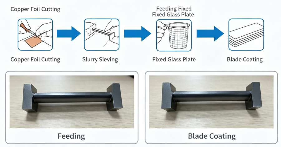
1. Adjustable Manual Doctor Blade Coater
- Precision manual adjustment of blade clearance to tune wet film thickness and active material loading
- The most widely adopted coating tool for coin cell and small pouch cell lab research
- Enables controlled variable coating weight comparative experiments

2. Non-Adjustable Manual Blade Coater
- Static blade gap with no thickness fine-tuning capability
- Low-cost, ultra-simple setup for preliminary rough formula screening only
3. Dip Coating for Porous Substrates (High Search Priority)
- Custom-built for 3D porous current collectors used in supercapacitor and high-surface-area electrode research
- No reliable method to calibrate coating thickness or uniform loading
- Prone to uneven pore infiltration and localized over-coating defects
4. Glass Rod Auxiliary Rolling Coating (Brief, Low Search Volume)
- Only suitable for ultra-trace material testing with limited raw material supplies
- Extremely poor coating uniformity leading to inconsistent electrochemical test results
- Not recommended for formal controlled comparative experiments
How to Choose a Lab Coating Method
- Coin cell standard research: Select adjustable doctor blade coating for consistent flat foil electrode thickness
- Supercapacitor porous electrode testing: Use dip coating for nickel foam, carbon cloth and titanium mesh substrates
- Solid-state lithium battery R&D: Manual blade coating is the primary lab method for thin solid electrolyte composite films
- High-surface-area porous electrode development: Dip coating is the preferred lab coating workflow
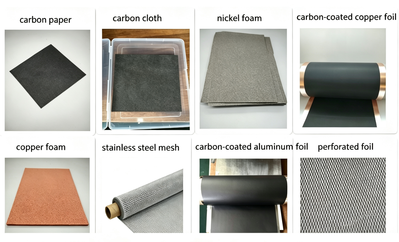
Full Catalog of Common Lab Current Collectors
How to Select the Right Current Collector
1.Flat coated foil (Industrial parallel baseline)
Carbon-coated copper foil, carbon-coated aluminum foil
2.Porous metal substrates (Supercapacitor & high-surface-area electrode research)
Nickel foam, copper foam, stainless steel mesh, titanium foil, titanium mesh, perforated metal foil
3.Carbon-based conductive substrates
Carbon paper, carbon cloth
Current Collector Matching Chart by Electrolyte System
| Electrolyte Category | Matching Current Collectors | Recommended Binders | Compatible Separators |
|---|---|---|---|
| Aqueous acid electrolyte | Stainless steel mesh, carbon cloth, titanium mesh, titanium foil | PTFE | Non-woven separator |
| Aqueous alkaline / neutral electrolyte | Nickel foam | PTFE | Cellulose separator, non-woven separator |
| Organic & ionic liquid electrolyte | Carbon-coated aluminum foil | CMC SBR, PVDF | Lithium battery separator, cellulose separator |
Lab-Specific Coating Issues (Lab-Only Troubleshooting)
1. Copper Foil Wrinkling on Manual Blade Coaters
- Ultra-thin bare copper foil lacks sufficient tensile rigidity
- Loose substrate fixation creates gaps between foil and glass base plate
- Unsieved hard particulate contaminants scratch and deform thin foil
Improvement Solutions
- Upgrade to thicker copper foil substrates for higher mechanical stability
- Secure foil tightly to glass panels to eliminate slack areas
- Complete full slurry filtration before every coating batch

2. Active Material Shedding on Lab Electrodes
- Excessively high single-side coating loading creates weak substrate bonding
- Unoptimized binder ratios within lab custom slurry formulas
- Overly fast oven heating triggers rapid solvent evaporation and binder separation
Improvement Solutions
- Switch to carbon-coated copper or aluminum foil for stronger interfacial adhesion
- Adjust CMC/SBR or PVDF binder proportions in slurry formulations
- Implement slow gradient low-temperature baking inside lab drying ovens
Internal cross-link anchor text: coating defect troubleshooting
If material shedding occurs after drying or calendering rather than during laboratory coating, refer to the industrial coating defect troubleshooting guide.
3. Uneven Nickel Foam Infiltration During Dip Coating
4. Material Shedding After Glass Rod Rolling Composite
- Uncontrolled uneven coating thickness from single dip coating cycles
- Localized over-coating creates fragile low-adhesion regions Improvement Solution: Fabricate uniform flat slurry films first, then transfer and roll-compound separately with porous nickel foam substrates
Lab Coating VS Pilot & Mass Production Coating Full Comparison Table
| Evaluation Index | Lab R&D Coating | Pilot & Industrial Mass Production Coating |
|---|---|---|
| Core Equipment | Adjustable/non-adjustable manual doctor blade coater, dip coating bench, glass rod rolling auxiliary gear | Integrated continuous unwinding-slot die coating-drying-rewinding production line |
| Substrate Format | Individually pre-cut small foil sheets, nickel foam, carbon cloth and porous mesh | Endless long continuous aluminum/copper foil rolls only |
| Primary Application Goals | Academic material screening, formulation comparison, small coin/pouch cell sample preparation | High-throughput mass manufacturing of commercial power battery electrodes |
| Coating Thickness Precision | Medium to poor (dip coating cannot reliably control loading) | Ultra-precise real-time online thickness scanning monitoring |
| Operating Speed | Static low-speed manual lab operation | Automated high-speed continuous running (up to 70 m/min optimized) |
| Supported Current Collectors | Flat foil all porous lab research conductive substrates | Restricted to standard commercial flat copper & aluminum foil |
Frequently Asked Questions
Conclusion
Related Products & Services
Use Canrd products and R&D services to turn battery knowledge into practical experiments.
Coin Cell Case
ProductCoin cell cases for validating materials and electrochemical concepts from the article.
Use coin cell cases in your next test →Sodium Electrolyte
CategoryElectrolytes for sodium-ion battery research, compatibility tests, and cell validation.
Shop sodium electrolyte for validation →Cell Fabrication
ServiceGet support building dry cells, assembled cells, or custom formats for R&D validation.
Request cell fabrication support →Experimental Materials
CategoryBrowse materials for follow-up experiments, benchmarking, and product development.
Browse experimental battery materials →