
How to Coat Battery Electrodes: Methods, Parameters and Common Defects
Introduction
Electrode coating is a critical step in lithium-ion battery manufacturing that directly determines electrode uniformity, adhesion, and final cell performance.
During coating, battery slurry must be uniformly applied onto metal foil and dried to form a stable active material layer. Any deviation in slurry properties, coating parameters, equipment conditions or drying process can create defects that affect capacity consistency, cycle life and production yield.
This guide explains lithium-ion battery electrode coating processes, major coating equipment, drying control methods and common coating defects. Engineers can learn how to identify root causes and optimize parameters to improve electrode quality and manufacturing stability.
1 Core Definition & Working Principle of Electrode Coating
Transfer Coating Standard Working Principle
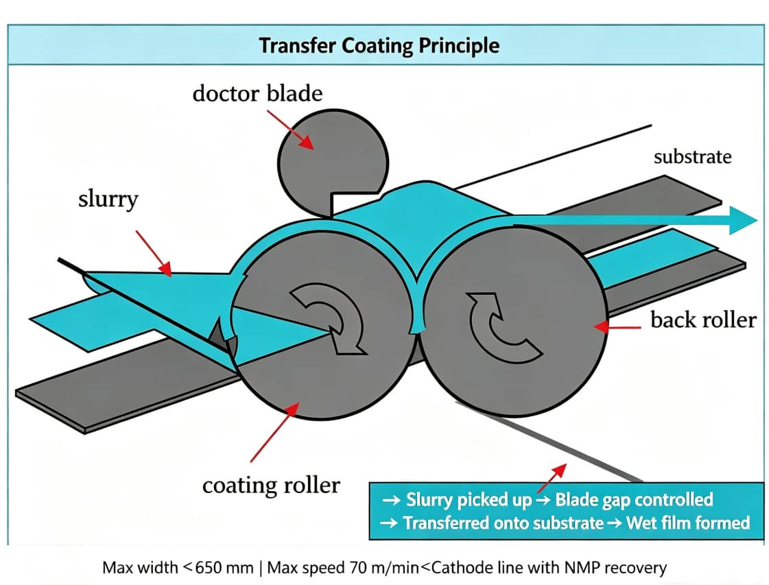
2 Four Main Coating Equipment Types & Complete Operation Procedures
2.1 Manual Adjustable Blade Coating (Laboratory Coin Cell Exclusive)
- Cut copper or aluminum foil into flat sheets;
- Fully stretch and fix foil without slack on smooth glass panels (core measure to avoid wrinkling);
- Filter slurry with 300~400 mesh screens and complete full vacuum degassing;
- Scrape coating at constant uniform speed;
- Transfer coated samples to segmented constant-temperature ovens for drying. Advantages: Low raw material consumption, freely adjustable coating thickness, fast formula screening for graphite and silicon-carbon anodesDisadvantages: Significant manual operation deviation, incapable of continuous roll-to-roll productionFrequent Lab Defects: Thin copper foil wrinkling, particle agglomerate scratches, uneven wet film leveling
2.2 Glass Rod Spreading Coating (Ultra-Low Raw Material Emergency Test)
2.3 Nickel Foam Dip Coating (Supercapacitor Specialized Process)
2.4 Industrial Roll-to-Roll Continuous Coating
2.4.1 Transfer Coating (3C Consumer Battery Mainstream Equipment)
2.4.2 Slot-Die Extrusion Coating (High-End EV Power Cell Production)
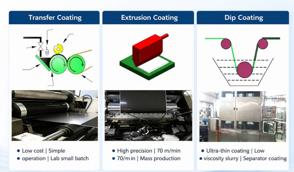
Coating Equipment Comparison Table
| Coating Type | Best Application Scenario | Core Advantages | Inherent Defect Risks |
|---|---|---|---|
| Adjustable blade coating | Lab formula small-batch testing | Low material loss, adjustable thickness | Thin copper foil wrinkling, manual operation deviation |
| Glass rod spreading | Emergency testing with trace materials | Zero equipment cost | Severe thickness unevenness |
| Transfer coating | 3C batteries & pilot production lines | Easy maintenance, supports intermittent blank coating | Flow marks under high slurry viscosity, blade scratches |
| Slot-die extrusion | High-energy power battery mass production | High precision, high running speed, few scratches | High procurement & maintenance cost, complex die cleaning |
| Nickel foam dip coating | Supercapacitor lab sample preparation | Fits 3D porous substrates | Uneven slurry pore penetration |
3 Complete Current Collector Matching Specifications
3.1 Conventional Lithium Ion Battery Flat Substrates
| Electrode Category | Standard Substrate Type | Common Thickness Range | Optimization Effect |
|---|---|---|---|
| NCM / LFP Cathode | Bare aluminum foil / carbon-coated aluminum foil | 9–16 μm | Reduce surface craters, improve PVDF coating adhesion |
| Graphite / Silicon-Carbon Anode | Bare copper foil / carbon-coated copper foil | 6–12 μm | Eliminate mass powder shedding, reduce foil wrinkling risk |
3.2 Supercapacitor Substrate Matching By Electrolyte System
| Electrolyte Type | Recommended Substrate | Matching Binder | Applicable Coating Method |
|---|---|---|---|
| Aqueous Acid System | Stainless steel mesh, titanium foil | PTFE | Low-solid-content blade coating |
| Neutral & Alkaline Water System | Nickel foam | PTFE | Multi-stage segmented dip coating |
| Organic / Ionic Liquid System | Carbon-coated aluminum foil | PVDF / CMC SBR | High-precision slot-die extrusion coating |
4 Standard 9-Step Roll-to-Roll Mass Production Coating Workflow
- Preheating Leveling Zone: Low temperature low air velocity to avoid instant bubble rupture and upward migration of SBR / PVDF binders
- Main Solvent Removal Zone: Medium constant temperature to evaporate most solvent and form stable coating skeleton
- Low-Temperature Cooling Zone: Eliminate internal drying shrinkage stress and control residual solvent or moisture content
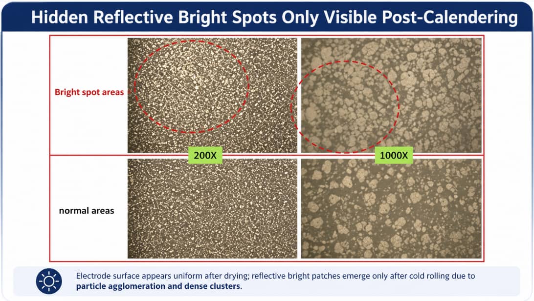
Step 8 Post-Drying Comprehensive Quality Control: Take offline samples to test areal loading and thickness; conduct small-scale calendering trials to find hidden agglomerate bright spots invisible to naked eyes.
Step 9 Constant-Tension Rewinding: Ensure neat roll edges without telescoping; mark slurry batch number and electrode type on each coil for full traceability.
Core Parameter & Defect Correlation Table
| Controlled Parameter | Core Function | Defects Caused By Abnormal Values |
|---|---|---|
| Slurry Viscosity | Adjust slurry fluidity and wet film leveling capacity | Excessively high: longitudinal flow marks, poor nickel foam penetration |
| Slurry Solid Content | Determine overall drying shrinkage amplitude | Too low: severe single-side electrode curling |
| Blade / Die Gap | Control single-side wet coating thickness | Excessively large: thick coating cracking |
| Coating Line Speed | Match oven solvent removal duration | Too fast: residual solvent exceeds standard limit |
| Oven Zonal Temperature | Regulate solvent evaporation rate | Too high: coating cracking and shedding |
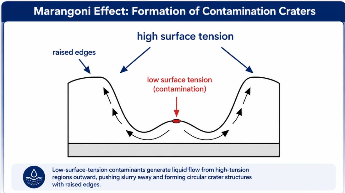
| Production Workshop Cleanliness | Isolate floating dust and lubricant pollutants | Dust & oil pollution: Marangoni effect surface craters |
5 Universal Quick Judgment Standard For All Coating Defects
| Defect First Visible Stage | Priority Inspection Items | Corresponding Typical Failures |
|---|---|---|
| Visible on wet film before oven feeding | Slurry performance, feeding pipeline, blade / die lip | Air bubbles, particle agglomerates, linear scratches, flow marks |
| Only visible after full drying treatment | Oven temperature, airflow, workshop dust & oil contamination | Coating peeling, electrode curling, pinholes, surface craters |
| Only exposed after calender compression | Slurry dispersion quality, local areal loading, coating adhesion | Reflective bright spots, partial coating delamination |
| Repeats at fixed horizontal foil positions | Doctor blade, coating roller surface | Fixed-position longitudinal scratches |
6 Complete Classification, Root Cause Analysis & Targeted Solutions For All Coating Defects
6.1 Coating Peeling & Mass Powder Shedding (High Frequency on Silicon-Carbon Anodes)
Visual Feature Description
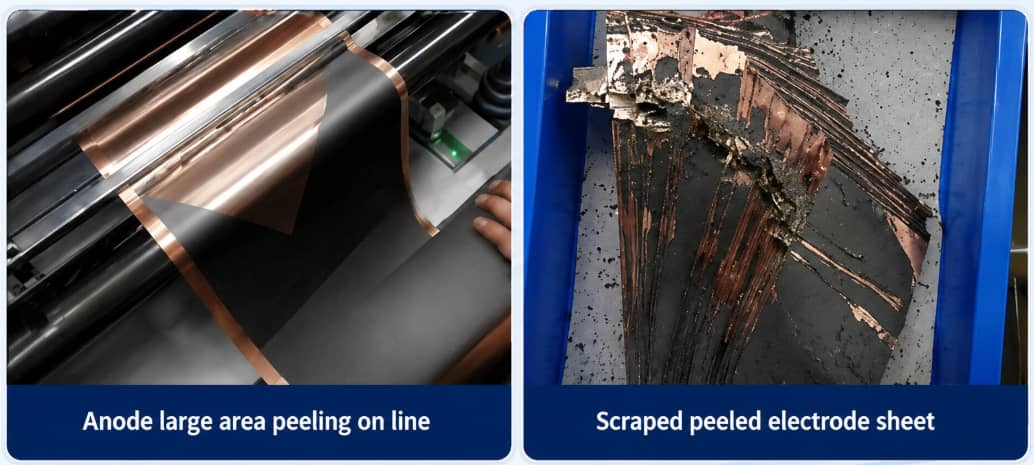
Multi-Dimensional Root Cause Breakdown
- Slurry formula factor: Insufficient CMC/SBR or PVDF binder proportion, mismatched binder grade; silicon-carbon particles expand up to 300% during charge and discharge cycles and further weaken inter-particle bonding force. Production test records confirm inadequate binder and SBR upward migration from rapid heating are the two primary shedding triggers for negative electrodes.
- Drying process factor: Excessively high preheating zone temperature accelerates solvent volatilization and drives SBR latex to migrate toward the coating surface, leaving almost no adhesive material at the foil-coating interface.
- Substrate factor: Bare copper or aluminum foil stained with processing oil and floating dust without carbon-coated buffer layer leads to weakened interfacial adhesion.
- Coating loading factor: Over-thick single-side wet coating generates massive shrinkage stress during solvent evaporation, tearing the complete coating network.
Systematic Implementation Solutions
- Formula optimization: Increase proportion of high-toughness dedicated SBR for silicon-carbon anode slurry; select high-adhesion copolymer PVDF for cathode formulas.
- Drying curve adjustment: Adopt full three-stage low-gradient heating to slow solvent evaporation and restrain binder upward migration.
- Substrate upgrade: Apply carbon-coated copper / aluminum foil for high energy density mass production to fundamentally boost interfacial bonding strength.
- Process split: Separate ultra-high areal loading into two independent double-side coating passes to reduce single-layer shrinkage stress.
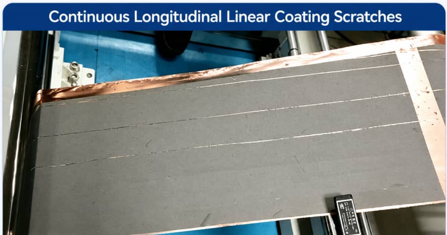
6.2 Continuous Longitudinal Linear Coating Scratches
Visual Feature Description
Multi-Dimensional Root Cause Breakdown
- Slurry filtration: Filter mesh aperture too large to intercept hard particle agglomerates formed during powder mixing;
- Coating head maintenance: Slurry crust forms after long idle storage and clogs the gap between blade and roller;
- Production operation: Long continuous running without regular solvent cleaning of blade lip surfaces.
Systematic Implementation Solutions
- Install double-layer composite filter screens at slurry feeding ports to block large hard particles;
- Form standardized operating rules: Clean blade lips with solvent every two continuous production hours;
- Limit idle storage duration of prepared slurry to avoid surface crust formation.
6.3 Transverse & Irregular Electrode Cracks After Drying
Visual Feature Description
Multi-Dimensional Root Cause Breakdown
Systematic Implementation Solutions
- Synchronously lower temperature setpoints of all oven zones;
- Moderately raise coating running speed to shorten high-temperature residence duration;
- Adjust slurry solid content to reduce overall drying shrinkage range;
- Optimize binder selection for high-thickness formulas to adopt higher flexibility varieties.
6.4 Single-Sided Coated Electrode Edge Curling
Visual Feature Description
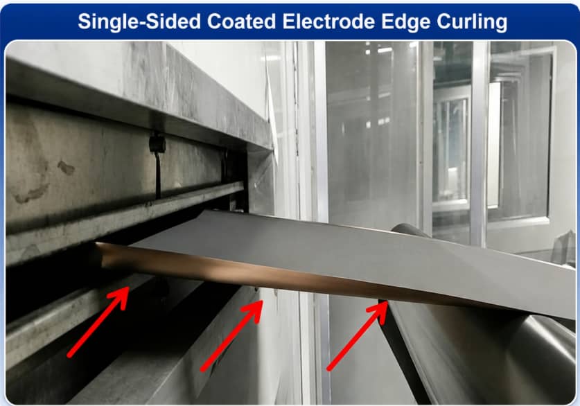
Multi-Dimensional Root Cause Breakdown
- Low slurry solid content creates excessive solvent loss and severe coating shrinkage;
- Over-high air velocity in preheating zone accelerates uneven solvent volatilization and forms tension difference between coated and bare foil sides;
- Binder varieties with high drying shrinkage coefficient amplify deformation risks.
Systematic Implementation Solutions
- Appropriately raise slurry solid content;
- Reduce upper and lower air speed of the first oven section;
- Replace low-shrinkage modified binders for curling-prone formulas.
6.5 Two Distinct Circular Pit Defects: Bubble Pinholes & Marangoni Contamination Craters
6.5.1 Bubble Pinholes
Visual Feature Description
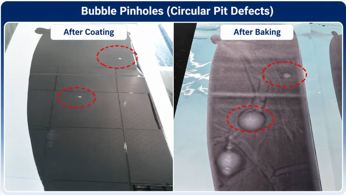
Root Cause Breakdown
Rectification Measures
6.5.2 Contamination Craters (Marangoni Effect)
Visual Feature Description
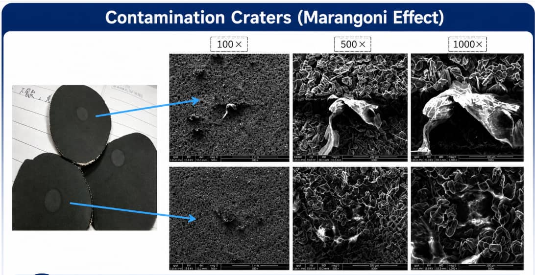
Identification Comparison Table
| Identification Feature | Bubble Pinhole | Contamination Crater |
|---|---|---|
| Pit Central Zone Condition | Clean, no foreign particles | Contains dust or lubricant impurities |
| First Appearing Stage | Visible on wet film before drying | Only forms after complete baking |
| Primary Inspection Target | Slurry degassing & conveying pipelines | Workshop dust prevention, equipment lubrication cleaning |
Rectification Measures
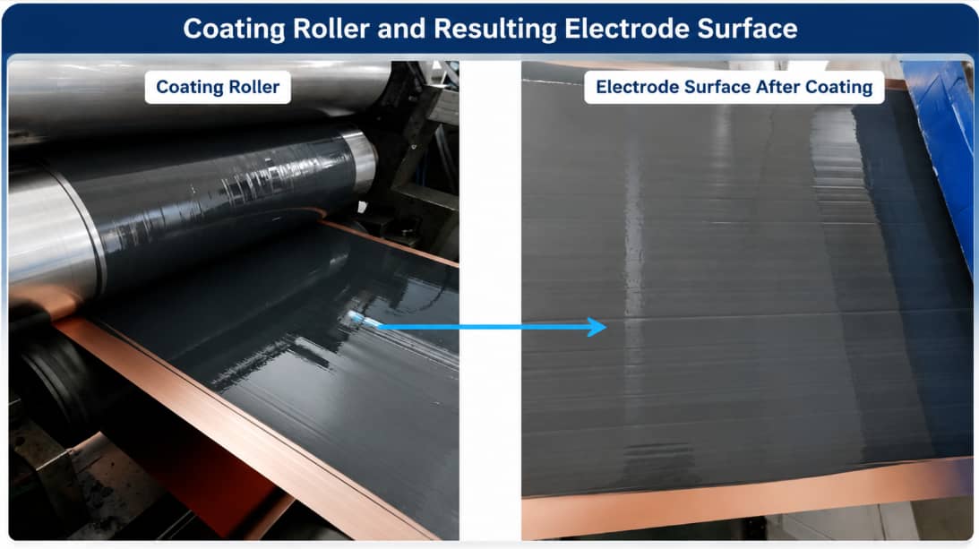
6.6 Parallel Flow Marks Caused By Excess Slurry Viscosity
Visual Feature Description
Multi-Dimensional Root Cause Breakdown
- Slurry viscosity exceeds upper process limit and loses natural wet film leveling capacity after passing blade gaps;
- Unstable slurry temperature creates real-time viscosity fluctuation during continuous production;
- Dry residual slurry adheres to roller surfaces and disturbs uniform wet film transfer.
Systematic Implementation Solutions
- Quantitatively supplement NMP (cathode) or deionized water (anode) to lower viscosity to qualified range;
- Equip slurry storage tanks with constant-temperature circulation systems to stabilize fluid properties;
- Fully polish and clean coating rollers before each production batch startup.
6.7 Hidden Reflective Bright Spots Only Visible Post-Calendering
Visual Feature Description
Multi-Dimensional Root Cause Breakdown
Systematic Implementation Solutions
- Adjust planetary mixer rotation and revolution speed ratio to extend high-speed dispersion phase;
- Form fixed inspection standards: produce comparative test pieces before and after calendering for every production batch to expose hidden agglomeration defects in advance.
6.8 Uneven Nickel Foam Slurry Penetration (Supercapacitor Exclusive Defect)
Visual Feature Description
Multi-Dimensional Root Cause Breakdown
Systematic Implementation Solutions
- Adjust formula solid content to reduce slurry viscosity and improve wettability to porous substrates;
- Adopt multi-layer thin dip coating with low-temperature baking intervals between each pass;
- Mass production advanced scheme: prefabricate complete electrode films then conduct hot-press lamination with nickel foam to solve infiltration defects fundamentally.
7 Cross-Process Defect Correlation: Slurry Mixing → Coating → Drying
| Slurry Mixing Abnormality | Derived Final Coating Defect |
|---|---|
| Incomplete powder wetting & insufficient particle dispersion | Longitudinal scratches, post-calendering bright spots |
| Insufficient vacuum degassing duration | Uniform pinholes distributed across full coil |
| Excess slurry viscosity | Parallel flow marks, poor nickel foam penetration |
| Undissolved PVDF / COMM room | Rough coating surface, large-area peeling |
| Long-term slurry static sedimentation | Uneven areal loading from coil start to coil end |
8 Standard Pre-Calendering Electrode Inspection Checklist
- Slurry Traceability Archive: Complete records of mixing batch number, viscosity, solid content, particle fineness and vacuum degassing duration;
- Visual Appearance Audit: No continuous scratches, large-area craters, penetrating pinholes or severe cracking;
- Dimensional Tolerance Test: Coating width, uncoated tab margins and intermittent blank gaps meet drawing standards;
- Physical Sampling Inspection: Single/double-side areal loading, coating peel strength and residual solvent content reach technical specifications;
- Rewinding Standardization: Neat coil edges without telescoping; clearly mark electrode type and coating side on each roll.
9 Standard Coating Troubleshooting Workflow
- Record complete defect information including shape, size, distribution and first visible production stage;
- Retrieve full test data of the corresponding slurry production batch;
- Inspect foil surface cleanliness, flatness and coating head blockage status;
- Optimize oven zoning temperature and airflow parameters according to defect types;
- Produce paired coating & calendering comparative test pieces to verify rectification effects;
- Conduct single-variable controlled production trials to confirm unique root cause.
Frequently Asked Questions
Q1 What is the core difference between transfer coating and slot-die extrusion coating?
Q2 Recommended gradient temperature window for graphite anode and NCM cathode drying?
Q3 Can calendering repair pinholes, craters and uneven coating thickness?
Q4 How to eliminate edge overflow during transfer coating production?
Q5 What causes severe single-side curling after electrode drying?
Q6 Why do massive air bubbles form after long slurry mixing?
Q7 Which substrate is suitable for high areal density silicon-carbon anodes?
Q8 Which coating process fits laboratory nickel foam supercapacitor sample preparation?
Conclusion
Related Products & Services
Use Canrd products and R&D services to turn battery knowledge into practical experiments.
Coin Cell Case
ProductCoin cell cases for validating materials and electrochemical concepts from the article.
Use coin cell cases in your next test →Sodium Electrolyte
CategoryElectrolytes for sodium-ion battery research, compatibility tests, and cell validation.
Shop sodium electrolyte for validation →Cell Fabrication
ServiceGet support building dry cells, assembled cells, or custom formats for R&D validation.
Request cell fabrication support →Experimental Materials
CategoryBrowse materials for follow-up experiments, benchmarking, and product development.
Browse experimental battery materials →