

 contact@canrd.com
 +86 18928276992
Slot-Die Coating Shim Guide: Thickness, Gap & Common Defects
Consistent lithium-ion battery electrode manufacturing relies on stable slurry formulation and precision coating equipment. Even with steady slurry viscosity, pump flow and coating speed, manufacturers still face coating width drift, longitudinal streaks and jagged electrode edges. One precision component that may contribute to these issues is the slot-die coating shim, although slurry properties and operating conditions must also be considered.
Fitted inside the slot-die head, the shim defines slurry outlet geometry, effective coating width and internal flow distribution. Its dimensional accuracy, flatness and assembly quality directly control coating repeatability.
A widespread industry misunderstanding: shim thickness does NOT directly set final electrode coating thickness. Shim geometry, die-to-web gap, slurry rheology, pump flow rate and coating speed work together as a coupled system. Mastering these relationships is critical for shim selection, defect troubleshooting, and scaling electrode coating from lab R&D to continuous roll-to-roll production.
1. What Is a Slot-Die Coating Shim?
A slot-die coating shim is a precision-machined spacer sandwiched between the upper and lower halves of the slot-die coating head.
Unlike simple mechanical gaskets only used for spacing, the shim forms part of the die’s internal slurry flow channel. Its cut opening shape controls where slurry exits the die and shapes your target coating pattern.
Core Functions
- Define effective coating width The shim opening sets the slurry discharge width and enables patterned coating such as multi-lane coating or reserved uncoated margins. Note: actual coated width still shifts due to slurry spreading and edge effects under different process conditions.
- Modulate slurry cross-web distribution Shim thickness and opening profile change internal flow resistance and pressure distribution. Together with the die manifold, they decide uniformity across the full coating width.
- Control electrode edge quality Well-machined, correctly installed shims deliver predictable coating boundaries. Burrs, misalignment or local shim deformation commonly trigger uneven edges, width deviation and localized coating defects.
- Maintain repeatable die assembly geometry Stable shim dimensions ensure consistent mechanical clamping after repeated disassembly, cleaning and reassembly — critical for mass production.
Installation reminder: The shim sits inside the die body. It is separate from the external clearance between die lip and moving current collector, known as die-to-web gap.
2. Shim Thickness vs Die-to-Web Gap: Key Distinction
Many battery engineers mix up these two core coating parameters. They serve entirely separate roles.
| Parameter | Main Function | Key Note |
|---|---|---|
| Shim Thickness | Controls internal slot geometry and flow resistance | Its effect on deposited coating must be evaluated within the stable coating window |
| Shim Opening Geometry | Defines coating width, lanes and patterns | Must match electrode design |
| Die-to-Web Gap | Clearance between die lip and moving substrate | Governs coating bead formation & stability |
| Die Lip Geometry | Affects slurry outflow and bead behavior | Determined by coating head hardware |
| Pump Flow Rate | Slurry volumetric delivery | Must match coating speed & width |
| Coating Speed | Substrate web travel speed | Controls slurry deposition per unit area and drying time |
Why shim thickness change does not directly equal coating thickness change
Slot-die coating is a pre-metered coating process. Under stable running conditions, average wet film thickness follows:
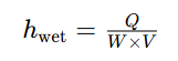
- h_wet = nominal average wet coating thickness
- Q = slurry volumetric flow rate
- W = effective coating width
- V = web coating speed
This relationship describes the nominal average wet-film thickness under steady-state conditions and does not account for cross-web thickness variation, edge effects or coating-bead instability.
With fixed width and line speed, higher slurry flow increases wet coating thickness. Changing shim thickness primarily affects internal flow geometry, pressure distribution and flow resistance. Its effect on the deposited coating must be evaluated within the stable coating window.
Practical takeaway: When electrode loading drifts out of spec, check slurry delivery, line speed and slurry properties before swapping shim thickness.
3. How to Select a Slot-Die Coating Shim
Start from your target electrode specification and coating process, instead of picking standard shim thickness blindly.
3.1 Confirm electrode coating pattern
Select shim geometry according to coating type: continuous coating, intermittent coating, single-sided or double-sided coating. Collect design inputs:
- Current collector material & width
- Target coated width
- Required uncoated foil margins
- Coating lane quantity and positions
- Electrode coating pattern
Note: Intermittent coating length and gap spacing are controlled by synchronized flow-switching systems, such as intermittent valves or pump modulation, together with web speed and, where applicable, coating-head movement. A shim alone cannot define intermittent coating segment geometry.
3.2 Check thickness uniformity & flatness
Precision shims require consistent thickness across the whole working zone. Local thickness variation or warping distorts internal die geometry and breaks cross-web uniformity. Inspect: flatness, local thickness tolerance, machining precision, deformation after cleaning and handling.
3.3 Examine cut edges and openings
Poor cut quality creates burrs, corner damage and rough surfaces. These imperfections may disturb local slurry flow, promote material accumulation and contribute to coating streaks. Inspect for edge chipping, surface contamination and dimensional deviation of cut openings before assembly.
3.4 Verify material compatibility
Shim material must resist your slurry solvent and cleaning chemicals.
- Cathode (LFP/NCM): PVDF NMP slurry system
- Anode (graphite): aqueous CMC/SBR slurry system
Different solvent chemistry and rheology demand matching shim material, surface finish and long-term dimensional stability. Stainless steel is widely used, but grade and chemical compatibility need validation for your process.
3.5 Account for cleaning and reassembly
Shims are clamped inside the die, not sliding wear parts. Cleaning scratches, improper assembly, corrosion and deformation are major failure modes. Always recheck reused shims even if nominal thickness remains unchanged.
Shim Selection Parameter Checklist Shim Thickness, Opening Width, Opening Geometry, Material Grade, Flatness, Surface Finish, Chemical Compatibility
4. Match Shim Selection to Electrode Slurry Chemistry
Some coating heads may accommodate both cathode and anode slurries, provided material compatibility, process requirements and strict cleaning procedures are verified to prevent cross-contamination. The shim must fit the full coating workflow, not just physical dimensions.
Cathode Slurries (LFP / NCM)
Cathode slurry contains active material, conductive carbon, PVDF binder and NMP solvent. Poor dispersion or agglomerates cause flow blockages and longitudinal streaks. Unstable viscosity ruins coating profile. Key checks: slurry filtration, viscosity & temperature stability, die cleanliness, cross-web flow distribution, solvent and drying setup.
Shim replacement cannot fix defects caused by agglomerates or dried slurry contamination.
Anode Slurries (Graphite CMC/SBR Aqueous System)
Water-based graphite anode slurry has unique challenges: graphite dispersion, CMC thickening, SBR binder stability and water evaporation. Aggressive drying triggers binder migration and weak foil adhesion. Wet coating may look uniform but fail after drying. Adjusting shim geometry will not resolve this root cause. Optimize slurry stability and drying profile first.
Coating Window Overview The stable coating window defines the operating envelope where consistent coating bead can form. It is jointly determined by coating speed, volumetric flow rate, die-to-web gap, slurry viscosity and surface tension. Operating outside this window leads to edge instability, air entrainment and cross-web non-uniformity.
5. Reference CANRD Electrode Specs: Coating Targets Guide Shim Design
Finished electrode specs define coating hardware requirements. CANRD reference lab electrodes have fixed mass loading and current collector parameters for process benchmarking.
| Parameter | LFP Cathode | Graphite Anode |
|---|---|---|
| CANRD Model | LF2201 | SM2201 |
| Electrode Type | Double-Sided LFP Cathode | Double-Sided Graphite Anode |
| Coating Mass Loading | 12.3 mg/cm² (±2%) | 5.8 mg/cm² (±2%) |
| Current Collector | 12 1 1 μm carbon-coated Al foil | 8 μmcopper foil |
| Electrode Size | 120 × 100mm | 120 × 100mm |
| Uncoated Margin | 10 mm | 10 mm |
Disclaimer: These are CANRD reference product specifications, not measured results from a specific slot-die shim trial. Confirm mass loading measurement basis and coating-side definition for each custom project. The listed final electrode dimensions should not be interpreted directly as the required shim opening dimensions.
Core logic: Final electrode specs define coating process parameters. Shim geometry only supports stable flow and target coating pattern. LFP cathode and graphite anode require separate process windows due to different slurry rheology and drying behavior.
6. Step-by-Step Slot-Die Coating Process Setup Workflow
Changing multiple variables at once makes troubleshooting nearly impossible. Follow this structured validation sequence.
- Lock target electrode specs: chemistry, foil type, coated width, mass loading and acceptance criteria before coating trials.
- Validate slurry quality: viscosity, solid content, dispersion, temperature. Filter and degas slurry to eliminate agglomerates and trapped air. Avoid misdiagnosing slurry defects as shim issues.
- Inspect and mount shim: confirm compatibility with coating head, check flatness, opening geometry and cleanliness. Assemble following OEM torque procedure.
- Stabilize slurry delivery: set initial flow rate and coating speed matching target loading. Verify pump consistency and feed pressure stability.
- Tune die-to-web gap: set lip-substrate clearance to form a stable coating bead without air entrapment, wavy edges or excess slurry buildup.
- Evaluate wet coating: check coated width, edge profile, streaks, bubbles and flow disturbance before drying. Wet inspection separates die-related defects from drying-induced issues.
- Test dried electrode: measure mass loading, thickness, dimension consistency, surface quality and coating adhesion against specs.
- Optimize iteratively: Conduct controlled single-variable trials or a structured Design of Experiments (DOE) study. Log successful parameter sets for repeatable production.
7. Common Coating Defects & Troubleshooting
Many coating defects originate from slurry preparation, equipment conditions or drying rather than the shim alone. Diagnose by defect morphology and distribution.
| Defect | Potential Causes | First Checks |
|---|---|---|
| Fixed longitudinal streaks | Slurry agglomerates, die lip contamination, local outlet blockage | Slurry filtration, die cleanliness, shim edge burrs |
| Cross-web loading variation | Uneven slurry flow, assembly misalignment, viscosity drift | Die alignment, shim flatness, pump & slurry conditions |
| Irregular coating edges | Mismatched shim opening, unstable coating bead, poor wetting | Shim alignment, coated width, die-to-web gap |
| Periodic transverse bands | Pump pulsation, web speed fluctuation, mechanical vibration | Pump performance, web drive, web tension |
| Pinholes / white spots | Entrapped air, incomplete degassing, drying bubbles | Slurry degassing, feed lines, wet film inspection |
| Cracks / powder shedding | Overdrying stress, weak adhesion, uneven binder distribution | Drying profile, binder formulation, foil surface |
| Progressive thickness drift | Slurry sedimentation, viscosity/temperature shift, unstable feeding | Slurry circulation, temperature control, pump stability |
When shim replacement should be considered
Shim replacement may be necessary when physical damage is identified or when a different opening geometry is required for process optimization.
- Permanent warping or loss of flatness
- Damaged, burred outlet edges
- Incorrect opening geometry
- Dimensions incompatible with target coating pattern
- Corrosion or mechanical damage impacting assembly
- Process optimization requiring revised coating width, multi-lane layout or improved cross-web flow distribution
If the shim remains dimensionally sound, adjust other process parameters first. For example, streaks from agglomerates can be fixed via filtration and cleaning; replacing a good shim wastes cost without solving the root problem.
8. How to Verify Electrode Coating Uniformity
Visually smooth electrode surfaces do not guarantee qualified coating. Use measurable metrics. CANRD divides coating quality checks into 3 groups: coating mass loading, dimensions & thickness, coating appearance & adhesion.
Coating Mass Loading
Cut samples of known area to calculate loading:
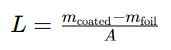
- L = coating mass loading
- m_coated = mass of coated sample
- m_foil = bare current collector mass
- A = coated sample area
For double-sided electrodes, this equation gives the combined coating mass loading of both sides. Individual A-side and B-side loadings require separate measurements or validated coating-removal procedures.
Electrode Thickness & Dimensions
Separate bare foil thickness, dry coating thickness, total electrode thickness and post-calendered thickness — these values describe different manufacturing stages and cannot be substituted. Also verify coating width and uncoated margin consistency.
Appearance & Adhesion
Visual inspection targets streaks, pinholes, cracks, edge fluctuation and local slurry accumulation. Adhesion testing confirms the dried coating survives downstream calendering and slitting. Online thickness/coating weight monitoring adds continuous cross-web and machine-direction variation data. Combine multiple metrics instead of relying only on visual checks.
9. Scale-Up: From Lab Coating to Continuous Roll-to-Roll Production
Lab-scale doctor blade coating works for early slurry screening with small material consumption. Continuous slot-die coating adds more constraints: stable slurry feeding, web tension, die alignment and continuous drying.
A lab-qualified slurry formulation still needs optimization for roll-to-roll lines. During scale-up, evaluate the full chain:
Slurry Preparation → Coating → Drying → Calendering → Electrode Inspection
The slot-die shim is only one component in this workflow; it cannot fix all coating quality issues independently.
10. CANRD Electrode R&D Support
Reproducible battery electrodes require matched raw materials, slurry mixing, coating technology and post-processing. CANRD supplies custom cathode and anode electrodes for battery R&D, covering multiple material systems, current collectors, coating patterns and formats.
For LFP, NCM, graphite and other battery material projects, clear specifications help define manufacturing routes and measurable acceptance criteria. Researchers may start with standard electrode sheets to test materials and cell performance before moving to custom electrode fabrication.
Conclusion
Slot-die coating shims are precision components defining internal slurry outlet geometry for repeatable lithium-ion electrode coating. Their thickness, flatness, opening design and machining quality shape coating behavior, but they cannot independently decide final dry coating thickness.
Reliable battery electrode production requires matching shim design with slurry rheology, feeding conditions, coating speed, die-to-web gap and drying performance. Best practice: start from target electrode specs, systematically validate process conditions, and use measured electrode quality data to drive optimization.
FAQ
Q: What is the purpose of a slot-die coating shim?
A: A slot-die coating shim defines internal slurry outlet geometry, effective coating width and coating pattern. It modulates internal slurry flow and enables repeatable die assembly.
Q: Does increasing shim thickness increase electrode coating thickness?
A: Not necessarily. Slot-die is a pre-metered process; wet film thickness is mainly controlled by slurry flow rate, coating width and coating speed. Shim thickness affects internal flow geometry, pressure distribution and flow resistance. Its impact on deposited coating must be assessed within the stable coating window.
Q: What is the difference between shim thickness and die-to-web gap?
A: Shim thickness is an internal dimension of the coating head. Die-to-web gap is the external clearance between die lip and moving substrate. The two interact but serve separate functions.
Q: How should coating shim dimensions be selected?
A: Select based on coating head design, slurry properties, target coating width, coating pattern and operating parameters. No universal shim thickness works for all battery electrode formulations. Key parameters include shim thickness, opening width, opening geometry, material grade, flatness, surface finish and chemical compatibility.
Q: Why does the length try to meet hard slot-die coating?
A: Root causes include slurry agglomerates, dried slurry deposits at outlet, contamination, unstable feeding or shim/die assembly defects. Complete slurry filtration and die cleaning should be checked before replacing the shim.
Q: Can one coating shim run both cathode and anode?
A: It may be feasible when coating geometry and operating parameters match. Material compatibility, process requirements and strict cleaning protocols must be validated to avoid cross-contamination.
Q: How can engineers confirm stable coating process?
A: Monitor coating mass loading, thickness variation, coated width, edge quality, surface defects and coating adhesion. Compare measured results with project acceptance criteria during trials and mass production.

