
Home/Resources/Knowledge/Battery Process/How to Control Moisture Before Electrolyte Filling in Lithium-Ion Pouch Cells
How to Control Moisture Before Electrolyte Filling in Lithium-Ion Pouch Cells
canrd July 23, 2026 128
Introduction
Vacuum baking and electrolyte injection are two of the most critical processes in lithium-ion pouch cell manufacturing. Vacuum baking eliminates residual moisture trapped inside sealed cells before electrolyte filling, while precise electrolyte injection delivers the ionic transport medium essential for stable SEI film growth. Poor control over either step triggers severe manufacturing failures: corrosive HF acid production, cell gas swelling, high internal resistance, low initial Coulombic efficiency, and drastically shortened battery cycle life.
What is vacuum baking for lithium pouch cells?
Vacuum baking is a high-temperature negative-pressure dehydration process that removes residual moisture from sealed aluminum-plastic pouch cells before electrolyte filling. It prevents LiPF₆ hydrolysis, HF corrosion and excessive gas generation during formation. Different cathode materials carry differentiated moisture control limits.
Why carry out electrolyte injection & post-injection standing after baking?
LiPF₆ electrolyte is extremely sensitive to water. Full dehydration via baking is mandatory; post-injection standing creates enough time for electrolyte to fully penetrate electrode and separator pores, avoiding insufficient wetting.
What is the long-term damage caused by excess moisture & HF?
Residual water reacts with lithium salt to generate HF. HF continuously erodes anode SEI film, consumes active lithium, triggers cell swelling, rising impedance and irreversible capacity attenuation over cycles.
Why Moisture & HF Are the Biggest Enemies of Lithium Batteries
This chapter targets high-intent search queries: why moisture ruins lithium batteries, LiPF6 water reaction, HF generation, SEI film damage mechanism
Irreversible Chemical Chain Triggered by Residual H₂O
H₂O (Moisture in cathode/anode/separator) ↓ Hydrolysis reaction with LiPF₆ electrolyte salt ↓ Generates corrosive hydrofluoric acid (HF) and organic byproducts (alcohol, CO₂, H₂) ↓ Two parallel destructive hazards
- HF corrodes the SEI film and dissolves cathode metal ions (Mn, Co, Ni)
- H₂ consumed during formation reduces initial Coulombic efficiency; accumulated gas bulges pouches
Long-Term Performance Consequences
- Trace HF continuously decomposes the uniform Li₂CO₃/LiF SEI passive layer on graphite anode, accelerating lithium plating
- Generated hydrogen & CO₂ stretch aluminum plastic seals, creating latent micro-short risks
- Uneven SEI growth causes huge capacity & internal resistance dispersion across batches
- Excess water permanently consumes active lithium, leading to rapid cycle capacity fade
Material-Specific Moisture Control Thresholds
Different electrode materials have distinct water absorption properties, so baking target ppm values differ:
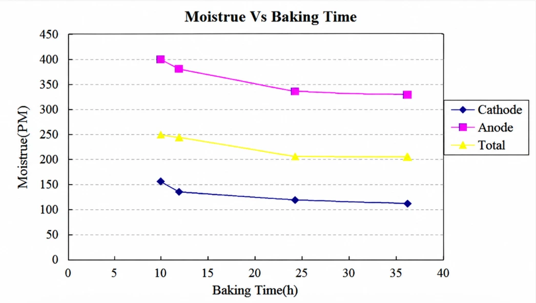
- LCO ternary cathode: ≤150ppm
- Graphite anode: ≤400ppm
- Whole bare cell standard (LCO/NCM): ≤250ppm
- High-BET materials (LFP, LTO): strong water absorption, overall cell limit ≤400ppm
Process Comparison Table
| Manufacturing Process | Core Primary Purpose |
|---|---|
| Vacuum Baking | Remove residual water trapped in electrodes & separators to block HF generation |
| Electrolyte Injection | Fill quantitative ionic transport medium based on cell capacity coefficient |
| Post-Injection Standing | Allow full electrolyte infiltration into electrode coating & separator pores |
| Post-Injection Hot Pressing | Reduce electrolyte viscosity to speed up uniform wetting |
| Cold Pressing | Stabilize wound/laminated layer spacing after liquid infiltration |
| Formation | Grow stable initial SEI film and activate lithium ions |
1 Why Vacuum Baking Matters
- Cuts off the H₂O-LiPF₆-HF destructive chemical chain, eliminating the root cause of long-term cell degradation
- Builds fully dry closed cavity compatible with ultra-moisture-sensitive LiPF₆ electrolyte
- Suppresses gas generation during formation, lowering pouch bulging scrap rate
- Standardized moisture limits guarantee consistent electrochemical performance batch to batch
- Protect anode SEI film integrity to extend usable cycle life
Without standardized vacuum baking, all upstream winding, stacking and packaging quality control efforts become ineffective once electrolyte is injected.
2 How Vacuum Baking Works
2.1 Core Working Principle
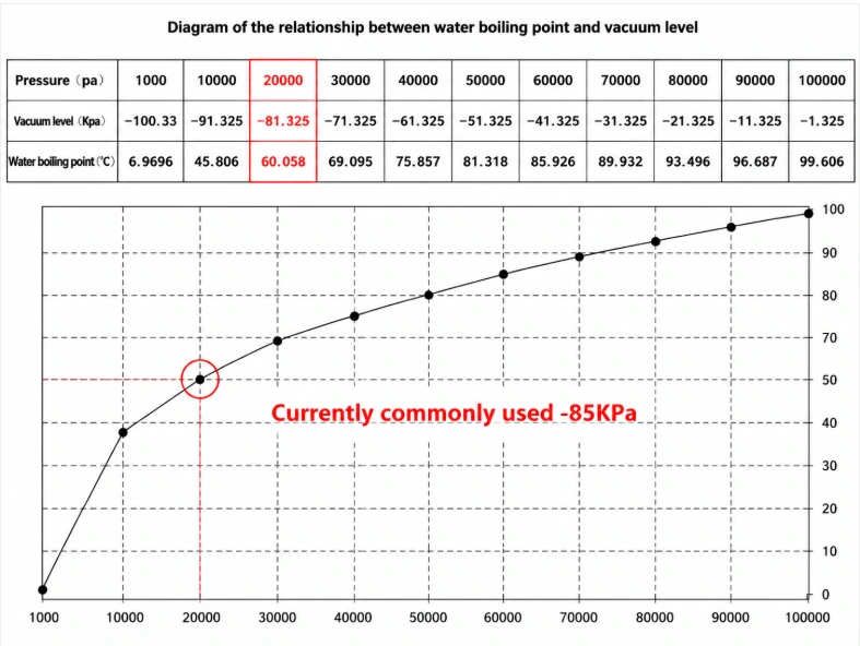
Sealed pouch cells are loaded into airtight ovens. The chamber heats cells while maintaining stable negative vacuum. High temperature accelerates water evaporation from electrode coatings, copper/aluminum foils and separators; continuous vacuum pumping extracts water vapor out of the cavity to hit material-specific ppm standards. Water boiling point drops sharply under low vacuum pressure, allowing effective dehydration below 85°C to avoid separator thermal deformation.
2.2 Typical Industrial Control Items
Targets search keywords: lithium battery vacuum baking parameters, baking specification standard
- Baking temperature ceiling: below 85°C (separator heat resistance limit)
- Stable vacuum level: mainstream mass production adopts -85KPa
- Constant temperature holding time (longer for thick laminated cells)
- Post-baking low-vacuum cooling duration
- Limited air exposure transfer time to injection station
- Material-based residual water ppm acceptance threshold
2.3 Main Production Equipment & Comparison
| Equipment Type | Heat Transfer Mode | Production Feature | Application Scenario |
|---|---|---|---|
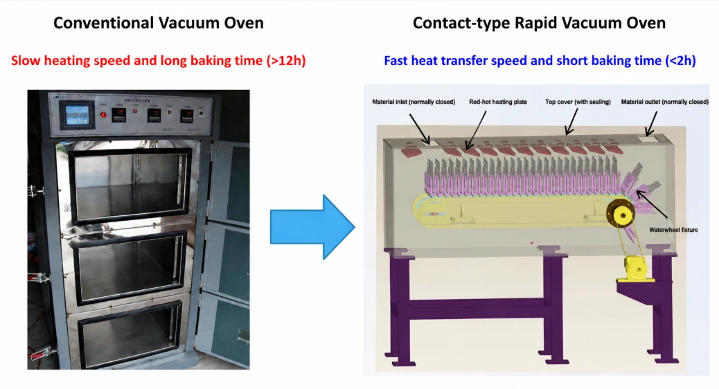
| Conventional Three-Door Vacuum Oven | Radiation only | Long cycle (>12h), low equipment cost | Small-batch pilot production |
| Contact Rapid Vacuum Oven | Conduction Radiation | Fast dehydration (<2h), high throughput | Large-scale EV battery mass line |
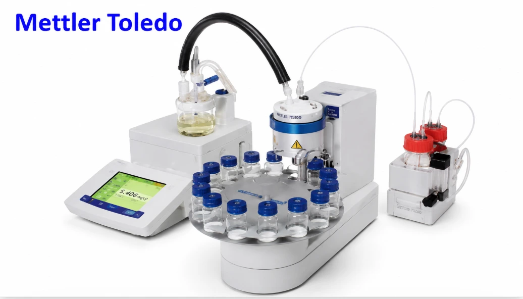
| Karl Fischer Moisture Tester | Chemical titration | Accurate ppm quantification | Offline batch sampling inspection |
| Real-Time Temp & Vacuum Monitor | Digital sensor tracking | Full process data traceability | All standardized production lines |
2.4 Standard Vacuum Baking Workflow
- Full appearance screening for aluminum-plastic pouches; reject pinhole, crack or incomplete sealing defective cells
- Arrange qualified cells neatly on scratch-proof transfer fixtures
- Load fixtures into fully sealed oven cavities and isolate external air
- Run automatic program: heat up → stabilize -85KPa vacuum → constant temperature hold
- Complete dehydration cycle, execute low-vacuum cooling to prevent secondary moisture absorption
- Unload cells and transport to glove box injection station within specified time window
2.5 Vacuum Baking Defect Troubleshooting Table
| Defect Phenomenon | Root Cause | Targeted Solution | Long-Term Electrochemical Risk |
|---|---|---|---|
| Excess residual water after baking | Insufficient holding time / vacuum pump air leakage | Extend baking cycle; repair vacuum pipeline sealing | Massive HF generation, severe capacity attenuation |
| Uneven dehydration across batches | Cells overcrowded blocking vapor circulation | Optimize fixture cell layout spacing | Wide internal resistance & capacity dispersion |
| Secondary moisture absorption post-baking | Transfer time limit exceeded, non-sealed trolleys | Adopt fully enclosed transfer carts | High formation K value, batch scrapping |
| Continuous oven temperature fluctuation | Aging heating tubes, drifted temperature probes | Replace heating components, re-calibrate sensors | Unstable residual water ppm across lots |
3 Electrolyte Injection & Post-Injection Standing Process
3.1 Core Function & Importance
Electrolyte acts as lithium ion transport medium between cathode and anode. Injection volume follows fixed coefficients: ~2.0g/Ah for LCO systems, ~3.0g/Ah for ternary materials. Under-dosage limits fast-charging capacity; over-dosage creates excess formation gas. After injection, mandatory standing allows electrolyte to fully infiltrate tiny coating and separator pores, eliminating local dry electrode zones. Standard standing schedule: room temp 24h high temp 12h.
3.2 Electrolyte Raw Material Quality Standards
Injection glove box must maintain dew point H₂O <0.1ppm; incoming electrolyte limits: moisture ≤20ppm, HF ≤50ppm, density tolerance ±0.003g/cm³.
3.3 Typical Industrial Control Items
- Single-cell injection weight tolerance calibrated per shift
- Glove box internal ultra-low dew point standard
- Injection needle positioning precision to avoid pouch film tearing
- Post-injection temporary vacuum sealing tightness
- Standing temperature & time fixed schedule
3.4 Injection Equipment Comparison Table
| Equipment Type | Core Application Scenario |
|---|---|
| Fully Automatic Glove Box Injection Line | EV & consumer cell mass production |
| Semi-Manual Injection Device | Laboratory prototype & small trial batches |
| High-Precision Analytical Balance | Daily pump weight calibration |
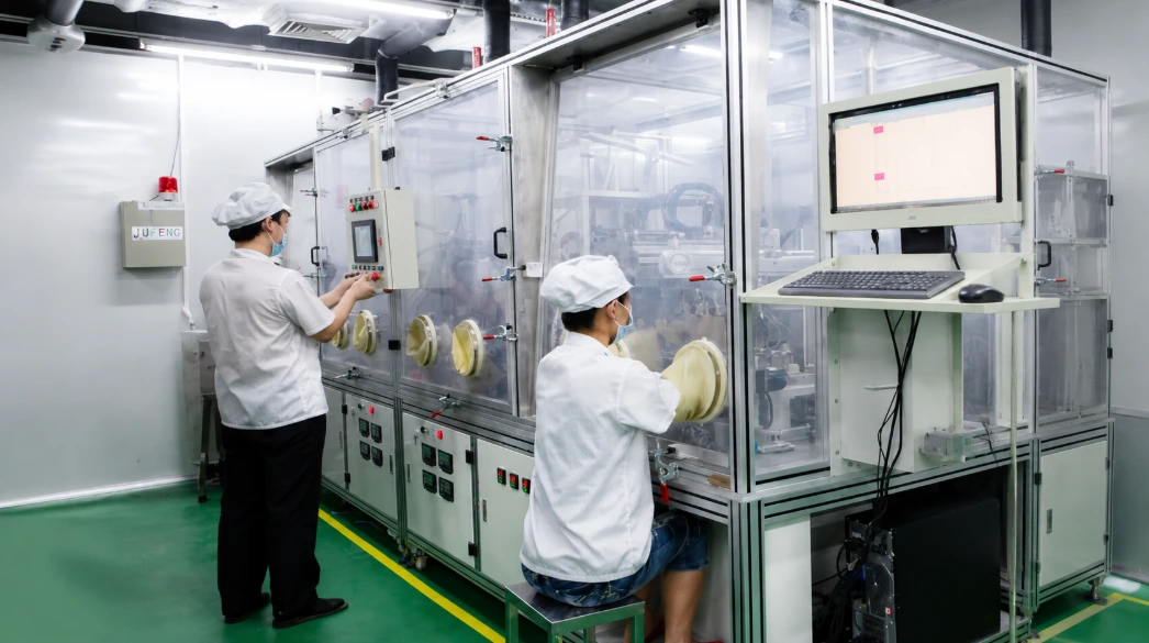
3.5 Standard Electrolyte Injection & Standing Workflow
- Transfer fully baked low-moisture cells into ultra-dry glove box
- Fix pouch injection port with positioning jig to prevent film rupture
- Set injection weight based on cell capacity coefficient and start quantitative pump
- Complete filling, apply temporary vacuum seal on nozzle opening
- Transport sealed cells to constant-temperature standing rack for scheduled wetting
- After standing cycle, send cells to integrated hot & cold pressing equipment
3.6 Electrolyte Injection Defect Troubleshooting Table
| Defect Phenomenon | Root Cause | Targeted Solution | Derived Cell Failure Mode |
|---|---|---|---|
| Under-dosed electrolyte | Injection pump calibration drift | Recalibrate pump with standard balance | Low discharge capacity, degraded high-rate performance |
| Over-dosed electrolyte | Incorrect single filling program parameters | Adjust pump volume setting | Severe pouch bulging during formation |
| Injection port liquid leakage | Jig offset, damaged pouch edge film | Re-align fixture, screen cracked pouches | Local dry electrode layers, hidden short risk |
| In-box electrolyte hydrolysis | High glove box dew point, poor airtightness | Replace desiccant, repair door seals | Early cycle capacity drop, rising impedance |
| Incomplete electrolyte wetting | Standing time insufficient | Extend high-temperature standing duration | Uneven SEI film growth, inconsistent capacity |
4 Post-Injection Hot & Cold Pressing
Core Function
Hot pressing moderately raises cell temperature to lower electrolyte viscosity and speed uniform pore infiltration; cold pressing stabilizes wound/laminated layer spacing after full liquid absorption.

Key Control Items
Hot pressing temperature, holding pressure, hot dwell time, cold cooling duration, upper/lower plate parallelism
5 Industrial Quality Inspection Standards
Mandatory offline & online inspection items implemented after baking and injection:
- Sampling water content test after baking Random batch sampling for every oven load; pass standard total residual moisture ≤200ppm, tested via Karl Fischer titration.
- Liquid injection weight recheck Randomly extract finished sealed cells for weighing to verify injection pump long-term precision drift.
- Full appearance visual inspection Check aluminum plastic shell for cracks, wrinkles, liquid seepage traces around sealed edges.
- Hi-pot insulation spot check Spot detect micro-short defects caused by oven thermal shrinkage or injection needle scratch damage on pouch film.
6 Advantages of Standardized Baking & Liquid Injection Process
- Complete moisture removal cuts off HF generation path, stabilizing electrolyte chemical properties and greatly extending cell cycle life.
- Standardized injection weight coefficients guarantee uniform lithium ion supply for all cells in one batch, narrowing capacity grading dispersion.
- Closed vacuum oven low-dew glove box system drastically reduce scrap rates of micro-short, bulging and self-discharge defective finished cells.
- Full parameterized programmable operation matches unmanned automatic production lines, cutting manual misoperation risks and mass manufacturing comprehensive costs.
7 Limitations & Industrial Optimization Directions
Existing Process Limitations
- Traditional baking ovens require long holding cycles, occupying large workshop floor space and restricting overall line throughput.
- Fully automatic glove box injection equipment carries high upfront procurement and daily maintenance expenses.
- Multiple cell transfers between oven, glove box and standing racks easily cause mechanical damage to aluminum plastic film.
Current Mainstream Industry Optimization Schemes
- Dual-layer continuous vacuum baking equipment shortens single batch dehydration cycle and boosts line capacity.
- Integrated winding-baking-injection linkage production line eliminates intermediate cell transfer steps.
- Online real-time water content monitoring sensors replace offline Karl Fischer sampling, improving inspection efficiency and real-time data feedback.
8 Process Linkage with Upstream Packaging & Downstream Formation
Upstream Aluminum-Plastic Packaging Impact
Aluminum-plastic film pinholes, stretch cracks or incomplete heat sealing form permanent moisture exchange channels. Even full standard vacuum baking cannot offset continuous water penetration during transfer.
Downstream Formation Process Impact
Unqualified baking residual water or uneven electrolyte wetting directly disrupt formation performance: excess water produces massive internal gas; incomplete infiltration creates irregular SEI film growth leading to wide capacity grading gaps.
Frequently Asked Questions
Q1 What is the difference in baking requirements between wound and laminated cells?
Z-fold laminated bare cells have far more electrode-separator contact interfaces that trap more moisture, requiring longer constant vacuum holding time than spiral wound flat cells to hit the same ppm limit.
Q2 Why must injection and standing be completed inside a low-dew-point glove box?
LiPF₆ electrolyte instantly hydrolyzes when exposed to atmospheric water vapor. Glove boxes maintain ultra-low humidity to protect electrolyte chemical stability during filling and wetting.
Q3 Can we skip vacuum baking if aluminum plastic film is fully hermetically sealed?
No. Cathode, anode and separator inherently absorb moisture during slitting, winding and stacking; sealed pouches only block external ambient water, not intrinsic material residual moisture.
Q4 What failure will insufficient post-injection standing cause?
Short standing time leads to incomplete electrolyte penetration into coating pores, resulting in uneven SEI film, low initial efficiency and large single-cell capacity differences after grading.
Q5 How does HF damage the SEI film on anode surface?
HF reacts with Li₂CO₃ main SEI component to generate insulating LiF precipitate, breaking the dense passive layer and triggering continuous active lithium consumption during cycles.
What Comes Next After Vacuum Baking & Electrolyte Injection Standing
After electrolyte filling, timed standing and hot-cold pressing homogenization, pouch cells enter the formation activation stage. Standard low-rate formation cycles build uniform anode SEI film, meanwhile generating internal reaction gas that requires degassing and secondary edge sealing treatment. All formation parameter control, gas extraction flow and secondary sealing specifications are fully covered in our dedicated follow-up manufacturing article.
Read Next: Lithium-ion Pouch Cell Formation & Degassing Complete Manufacturing Guide
Conclusion
Vacuum baking, electrolyte injection and post-injection standing form the complete moisture control & electrolyte wetting chain between aluminum-plastic packaging and electrochemical formation. Vacuum baking eliminates material residual water to block the H₂O-LiPF₆-HF corrosion cycle; precise quantitative injection plus timed standing ensures full electrode pore infiltration for consistent lithium ion transport.
Manufacturers must deploy differentiated vacuum baking holding durations for wound versus laminated cells, strictly control glove box dew point and standardized standing schedules. Adopting optimized continuous baking and integrated linkage lines can reduce transfer damage, lower scrap rates, stabilize internal resistance and extend cycle lifespan for consumer, automotive and energy storage lithium pouch cells.
Previous
How Are Lithium-Ion ...Related Products & Services
Use Canrd products and R&D services to turn battery knowledge into practical experiments.
Coin Cell Case
ProductCoin cell cases for validating materials and electrochemical concepts from the article.
Use coin cell cases in your next test →Sodium Electrolyte
CategoryElectrolytes for sodium-ion battery research, compatibility tests, and cell validation.
Shop sodium electrolyte for validation →Cell Fabrication
ServiceGet support building dry cells, assembled cells, or custom formats for R&D validation.
Request cell fabrication support →Experimental Materials
CategoryBrowse materials for follow-up experiments, benchmarking, and product development.
Browse experimental battery materials →